CommScope ERA
®
CAP MX Medium Power Carrier Access Point Installation Guide M0203A5A_uc
Page 48 © November 2020 CommScope, Inc.
Installing CAP MXs
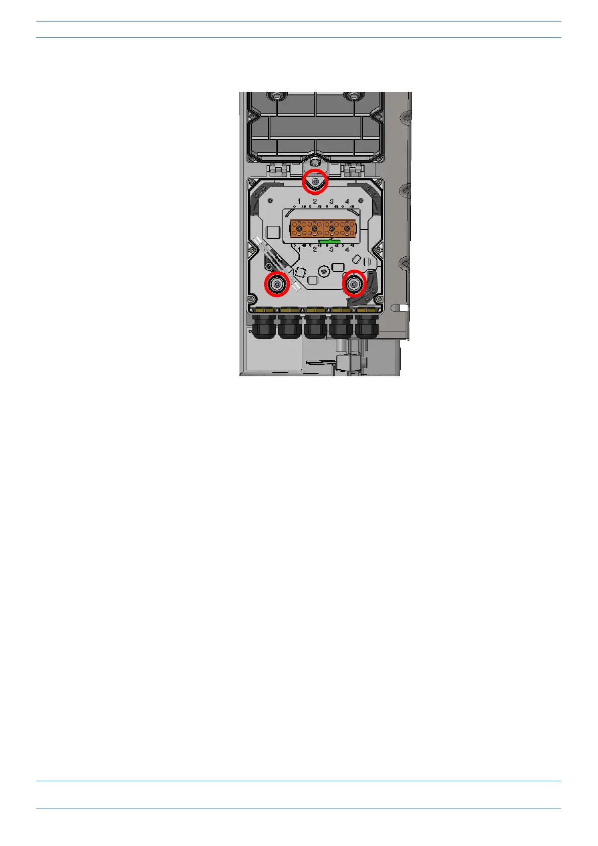
4 Attach an M4 x 25 pan-head screw to the upper hole, and two M4 x 25 pan-head screws to the holes in the
lower corners of the Splice Box.
5 Close the Splice Box.
6 Replace the six neck screws that you removed from the front cover of the Splice Box in Step 2 on page 47.
7 Go to "Grounding the CAP MX” on page 51.