M0203A5A_uc CommScope ERA
®
CAP MX Medium Power Carrier Access Point Installation Guide
© November 2020 CommScope, Inc. Page 5
CAP MX Overview
CAP MX OVERVIEW
This installation guide describes the Medium Power Carrier Access Point (CAP MX), which interfaces via an
optical link with a Classic CAN, or with a TEN. This allows the CAP MX to provide data over Single-Mode Fiber
(SMF), or Multi-Mode Fiber (MMF). Power for CAP MXs is provided over embedded AC/DC (AC version) or
remotely through hybrid fiber (DC version).
On the downlink, the CAP MX converts data arriving at the CAP MX to analog signals and sends them to the
Antenna port. On the uplink, received signals are digitized and serialized into data streams, which are sent
back to the Classic CAN or TEN. Each CAP MX can provide RF coverage for up to seven specific frequency
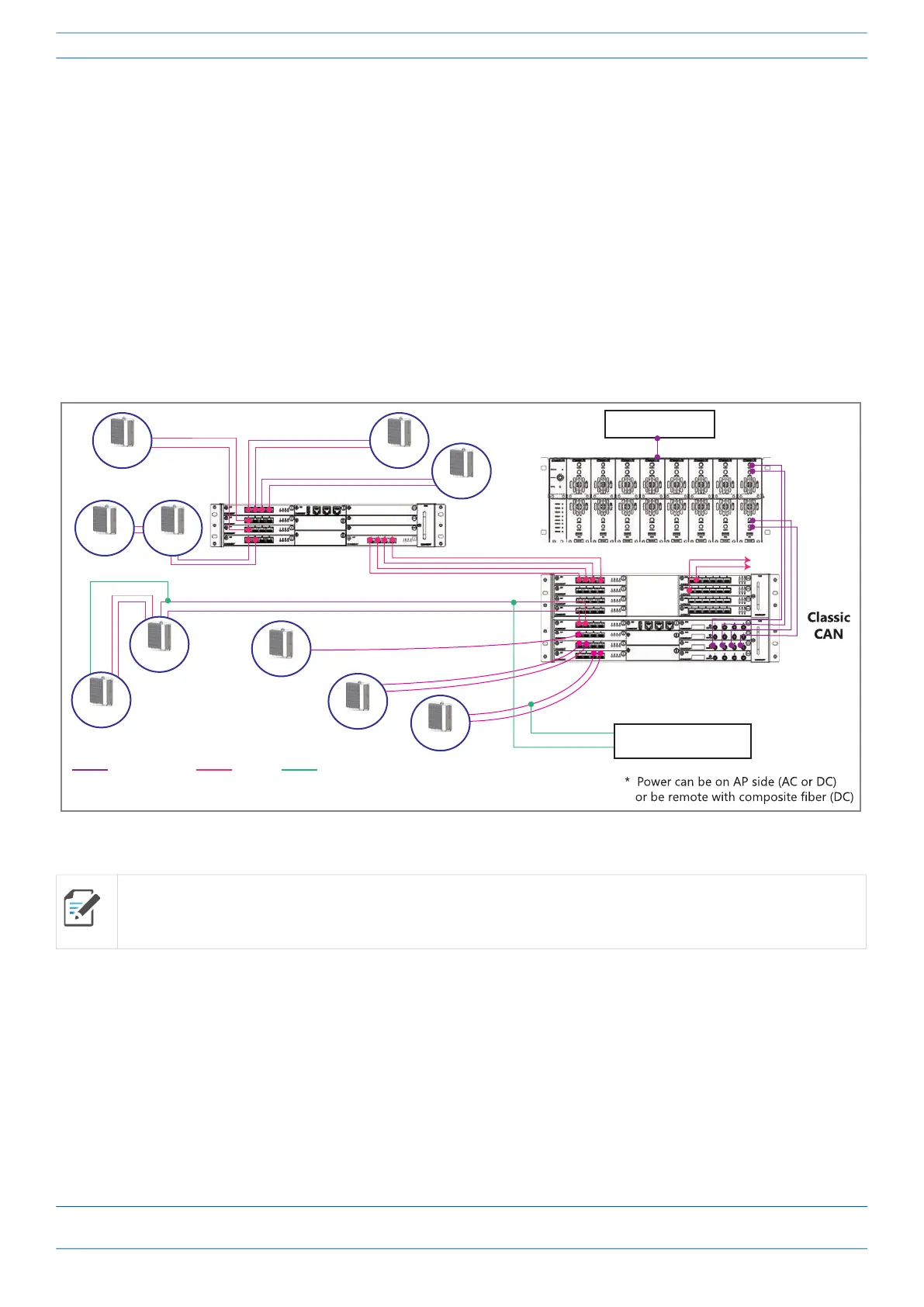
bands. Figure 1 shows how a double CAP MX configuration can be deployed in an ERA system.
The CAP MX RF bandwidth, with only a primary fiber connection to a CAN or TEN, is 320 MHz. Connecting a
secondary fiber cable, in parallel to the primary fiber connection, increases the RF bandwidth to 480 MHz.
The secondary fiber connection must be sourced from the same CAN or TEN as the primary fiber connection.
Figure 1. CAP MX in an ERA System using a Classic CAN
The CAP MX
• is passively cooled and operates within the following temperature ranges:
-33°C to +55°C (-27.4°F to 131°F)
• is rated for indoor and outdoor (IP66) installations; see also "Determine the Mounting Site” on page 23
• has a typical power consumption of 300W; see also "Determine the Power Consumption of the CAP MX”
on page 22.
All APs can only connect to a TEN or a Classic CAN. APs cannot connect to a Switching CAN or to a WIN.
e-POI
To BBU
eNode B
Coax cable Fiber Power
TEN
CAP MX
CAP MX
CAP MXCAP MX
CAP MX CAP MX
CAP MX
CAP MX
CAP MX
CAP MX
Power*