CommScope ERA
®
CAP MX Medium Power Carrier Access Point Installation Guide M0203A5A_uc
Page 26 © November 2020 CommScope, Inc.
Installing CAP MXs
Unpack and Inspect the CAP MX and Optional Accessories
1 Inspect the exterior of the shipping container(s) for evidence of rough handling that may have damaged
the components in the container.
2 Unpack each container while carefully checking the contents for damage and verify with the packing slip.
3 If damage is found or parts are missing, file a claim with the commercial carrier and notify CommScope
Technical Support (see "CMS Global Technical Support” on page 63). Save the damaged cartons for
inspection by the carrier.
4 Save all shipping containers for use if the equipment requires shipment at a future date.
Wire an Optional Hybrid Fiber Splice Box
1 Obtain the Hybrid Fiber Splice Box Kit (CommScope PN 7693816-xx).
2 Follow the steps in "Unpack and Inspect the CAP MX and Optional Accessories” on page 26.
The steps in this section pertain only to those installations that require the use of the optional Hybrid
Fiber Splice Box to provide fiber and power to the CAP MX. If the optional Hybrid Fiber Splice Box is not
required for this installation, skip to "Mount the CAP MX” on page 30.
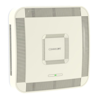
3 Open the Hybrid Fiber Splice Box and remove the installation kit that is
inside.
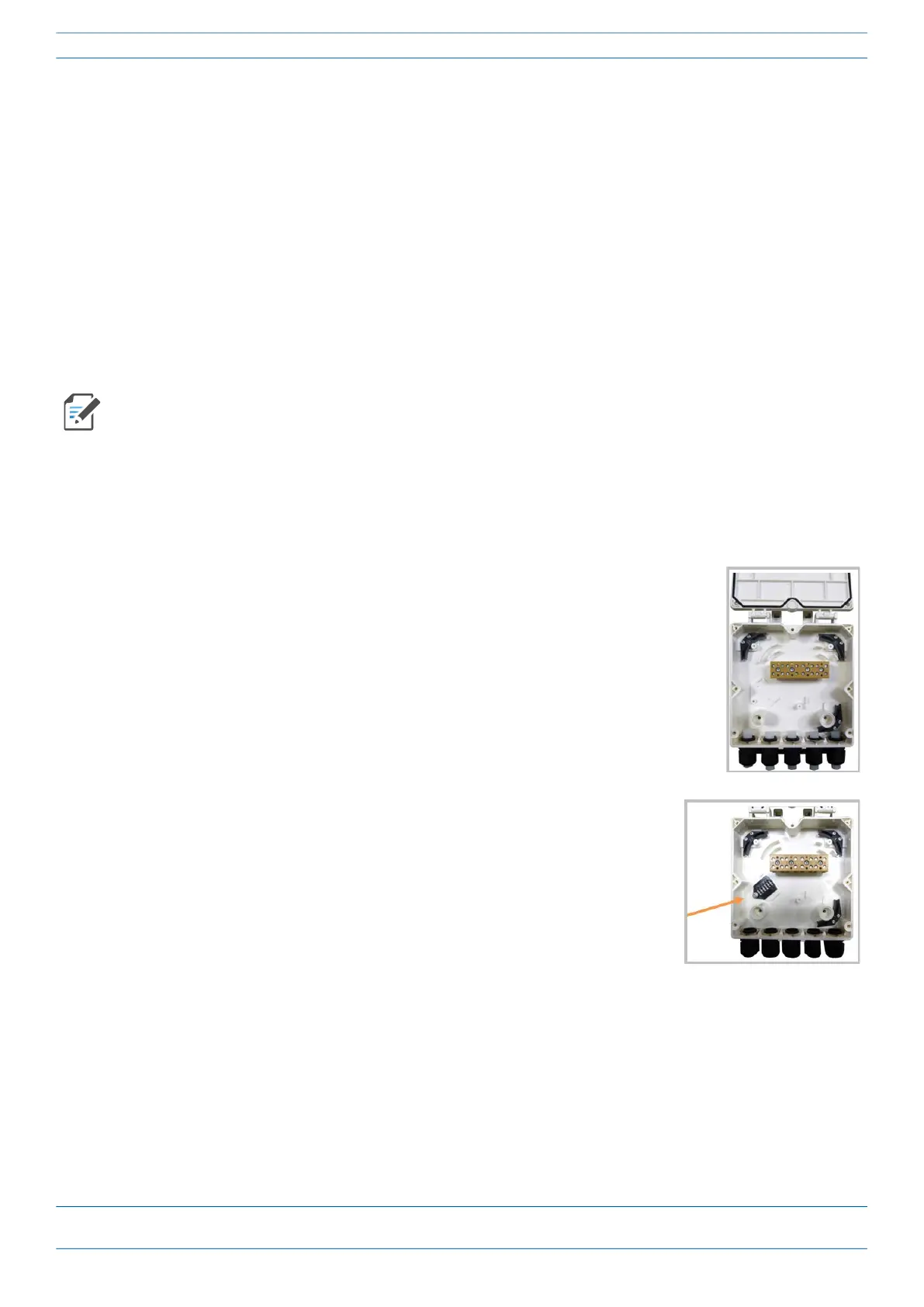
4 Using the parts from the Hybrid Fiber Splice Box, insert the Splice Holder
and fasten it using a PTK 30x6 screw and one M4 washer.