CommScope Instruction Guide
860647713, Rev B, V.05
Page 10
38 Pages
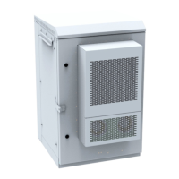
► Rear Panel Removal and Installation
Prior to panel removal or installation, use door key (Figure 11) that ships with cabinet to open or close
1/4-turn latches when removing or installing a panel, Figure 9.
Note: Rear panel has ground cable attached on the inside of the panel.
Removal and Installation (Figure 9)
■ Removal
— Turn panel latches to open position and pull out top of panel first; then tilt panel out and pull up on
panel to remove the panel from the opening.
— To remove the panel from the cabinet, disconnect ground cable from the green connector shown
in Figure 9. Prior to replacing the panel, make sure to reconnect ground cable to green connector.
■ Installation
— Tilt panel bottom in and insert bottom into cabinet; press into panel and close latches.
Figure 9. Rear Access Panel Removal and Installation, Ground Cable Disconnect
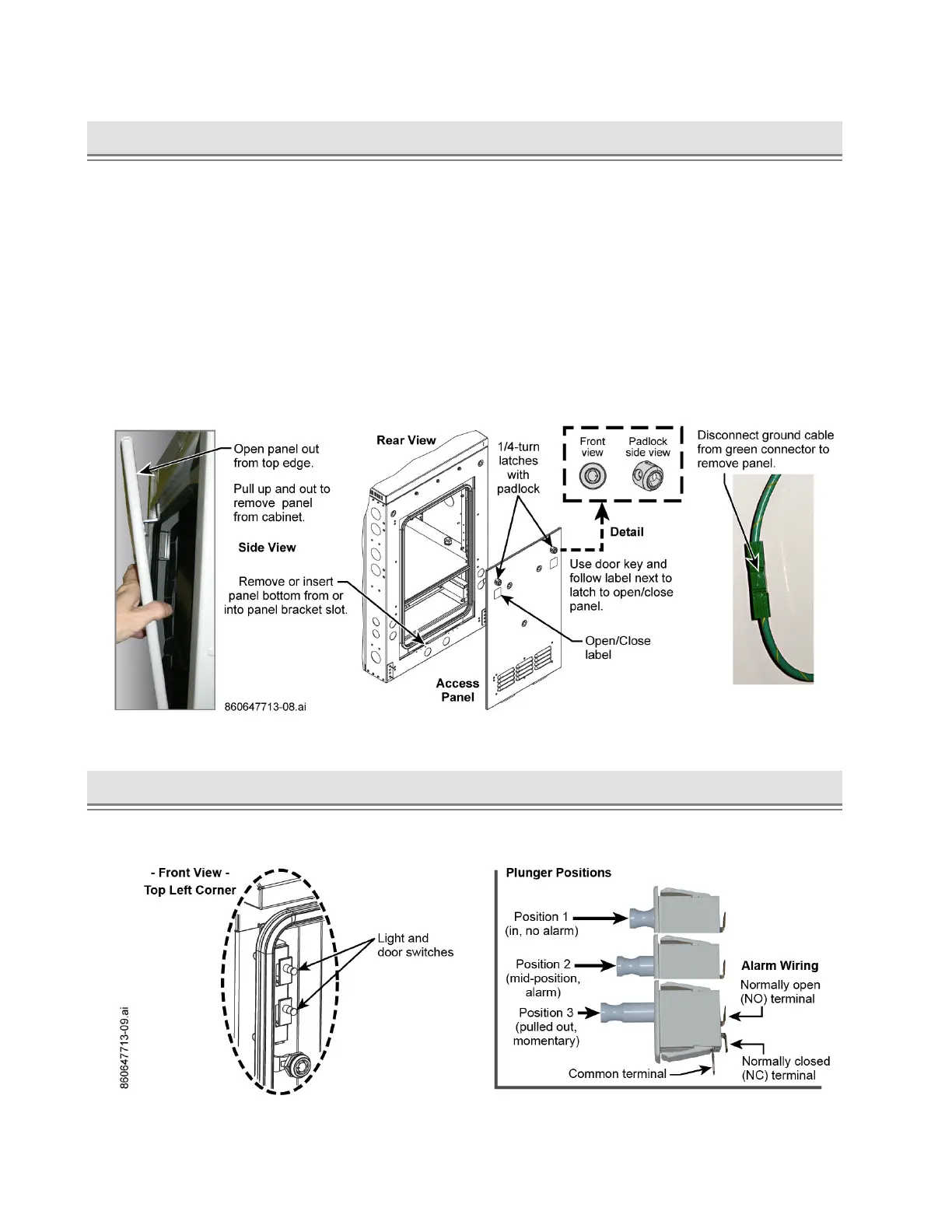
► Door Intrusion Alarm Switch
The light and door intrusion switches are on the top left corner of the doorframe inside the cabinet.
Connect the door alarm as required to an alarm center, Figure 10.
Figure 10. Light and Door Intrusion Switches