CommScope Instruction Guide
860647713, Rev B, V.05
Page 32
38 Pages
► Battery Installation
Battery installation consists of:
► Step 1 – Cabinet Preparation Prior to Installation, VRLA
► Step 2 – VRLA Battery Installation
► Step 1 – Cabinet Preparation Prior to Installation, VRLA
Prior to installing VRLA batteries:
1. Open the door and verify cabinet connection to site ground.
2. For initial cabinet installation, ensure all cabinet power is OFF, including the power shelf.
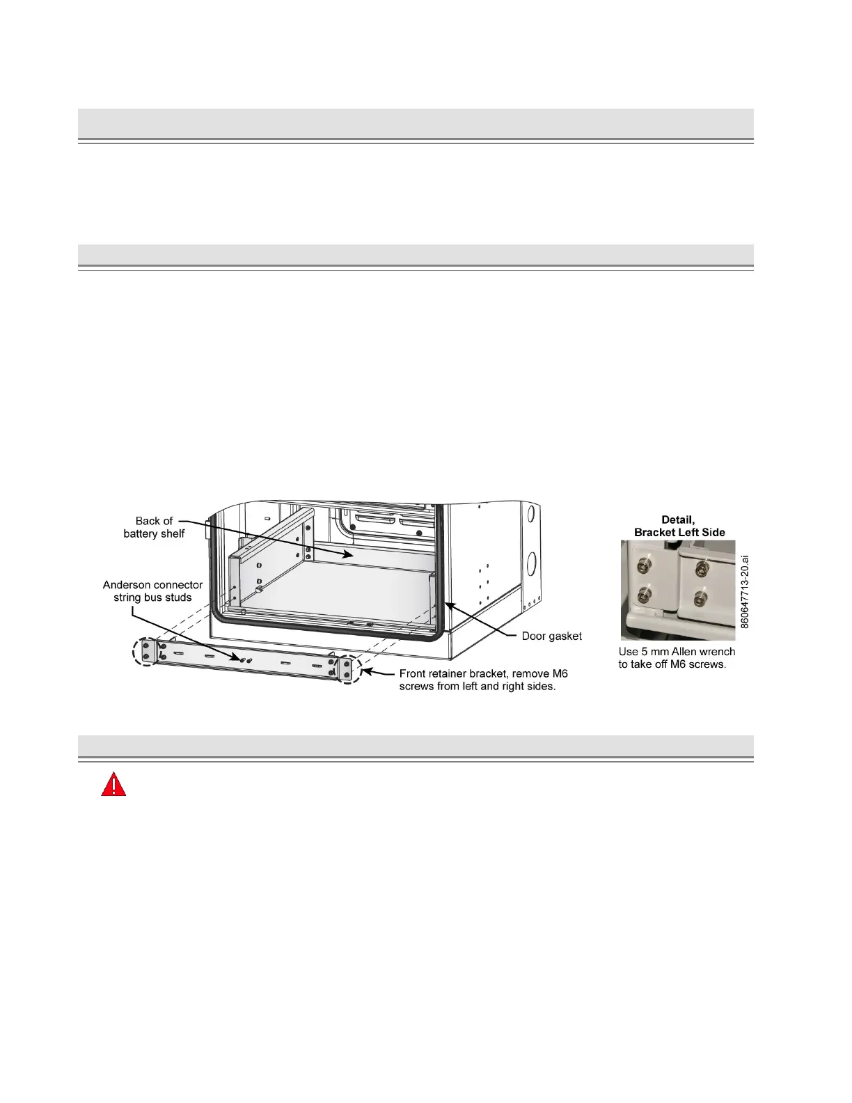
3. Remove the battery front retainer bracket, Figure 41.
■ Take off the four M6 screws on left and right sides of the bracket and retain hardware for
reinstallation.
Note: If cabinet configuration uses Anderson connectors, remove string bus connector from
bracket and retain hardware for reinstallation; Figure 41, Figure 42. For standard lug
connection to +RTN and -48 V terminals (Figure 44), set cables clear of batteries and do
not remove protective covers until ready to connect.
4. Cover the door gasket on the lower door flange to protect it from any damage, Figure 41.
Figure 41. Front Battery Retainer Bracket Removal, VRLA Installation
► Step 2 – VRLA Battery Installation
Important:
■ Do not remove protection boots from the batteries and battery cables until ready to connect.
■ Terminate each cable to correct terminal. Cable connectors have marked polarities and color
codes; red on positive cable (+RTN), black on negative cable (-48 V).
■ Have the SD on hand to look at for battery and thermal probe connection details.
■ If installing batteries in a battery only cabinet also follow instruction on routing and connection to
a CMC power cabinet using battery interconnect kit 860651309 in the next section
Battery Interconnect Kit 860651309, Installation – CMC-28/35.