CommScope Instruction Guide
860647713, Rev B, V.05
Page 34
38 Pages
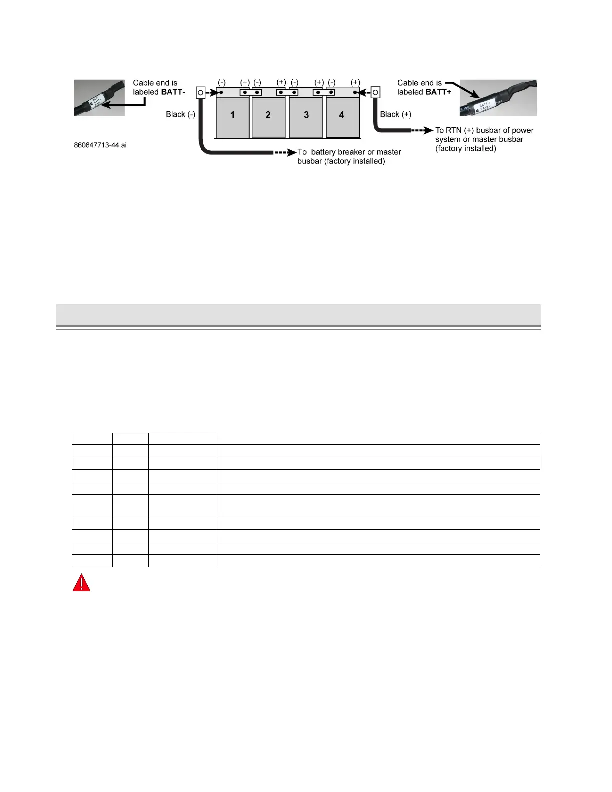
Figure 44. Battery String Cable Connections, Example with Lugs
6. Dress the battery cables and thermal probe wires as required.
7. Reinstall the battery front retainer bracket on each shelf, Figure 41.
■ If using Anderson connectors: Fasten string bus connector (to power system) onto retainer
bracket per Figure 43; then fasten battery string connector to battery string bus connector.
8. Remove all installation debris, tools, and extra hardware from inside the cabinet.
9. Make sure you can close and open the door without any interference from battery cables.
10. Turn-up power and configure power system controller for VRLA batteries and total number of strings.
► Battery Interconnect Kit 860651309, Installation – CMC-28/35
The battery interconnect kit allows DC load connection from a CMC battery cabinet to a CMC power
cabinet. This kit arrives inside each CMC-28/35 battery cabinet as provided by the factory at time of
manufacture.
■ Have the SD on hand to look at for battery and thermal probe connection details.
■ Verify all parts per Table H are in the kit. For missing or damaged parts call technical support at
1-800-255-1479 (Option 3 / Wireless Products).
Table H. CMC-28/35 Battery Interconnect Kit 860651309, Parts
Bushing, Insulated, 2-Inch Rigid Conduit
QS873A Thermal Probe (108987611)
Cable Assembly, Probe Interconnect, 10 FT (CC848822321)
Locknut, Conduit, Sealing, 2-Inch
Probe Interconnect, QS873A Battery Probe To Controller, 20 FT
(CC109157434)
Probe Interconnect Cable, 20 FT (850027334)
Cable Assembly, DC Power Interconnect (Battery Load)
Conduit, 2-Inch, 6-Inch Nipple
Coupling, Conduit, 2-Inch
Warning:
Risk of Electric Shock. Shut of all battery breakers prior to making any DC load connections
(customer feeds). For busbar assignments, see the cabinet SD for busbar landing assignments.