Material ID 860647713
Rev B, V.05, February 2022
Page 35
38 Pages
► To install kit 860651309:
Note: Have battery and power cabinet SDs in hand for reference and details. This procedure shows
how to install a CMC-28/35 battery cabinet on the right side of the power cabinet.
1. Prior to battery cabinet installation:
a. Remove rear panel (page 10) and cabinet solar shield (page 12).
Note: Do not remove master busbar cover at this time.
b. Remove battery and power cabinet knockouts.
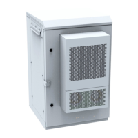
■ Matching CMC Cabinets (same height) – use the upper two wall knockouts between each
cabinet, Figure 45 and Figure 47, as knockouts are aligned to each other.
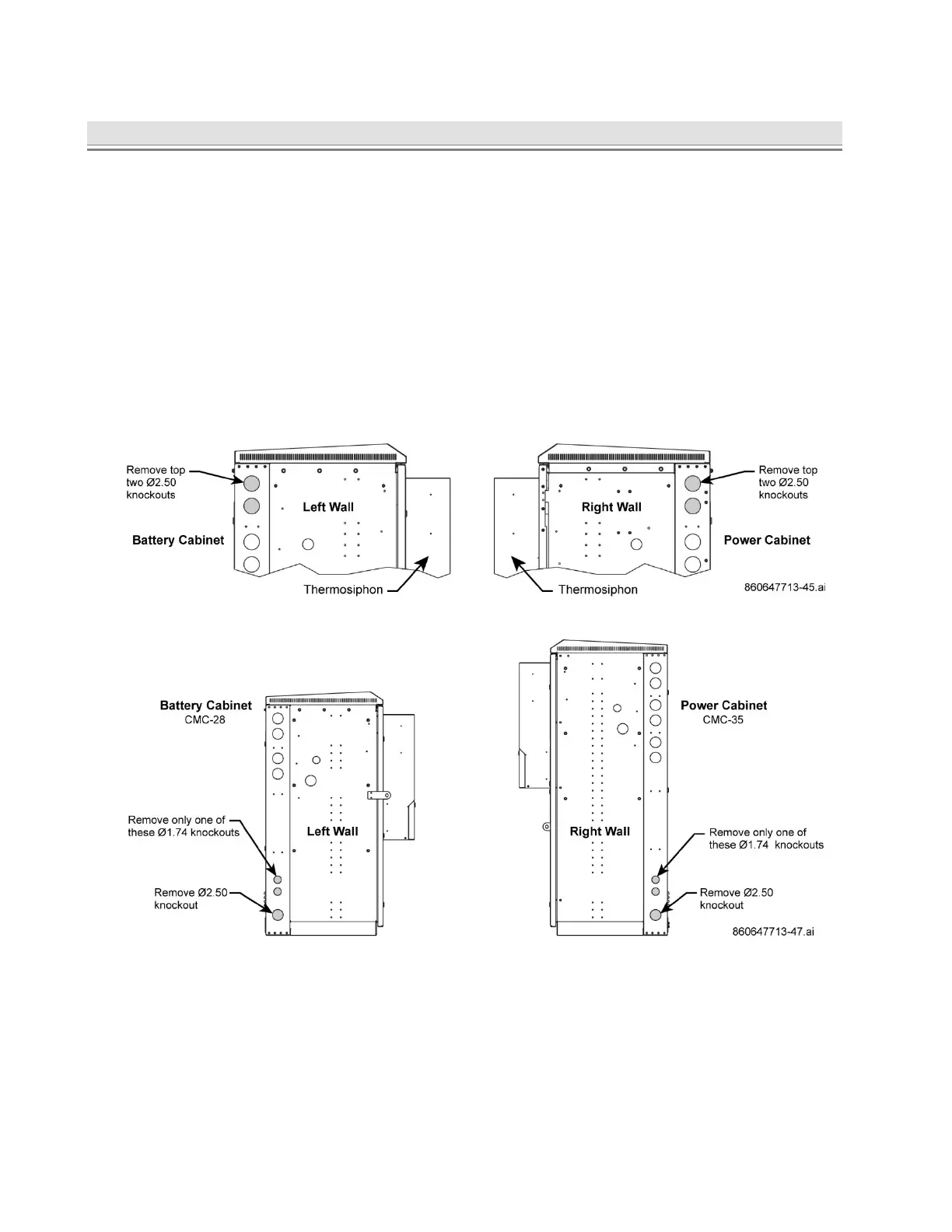
■ Non-Matching CMC Cabinets (different heights) – use the bottom two left wall knockouts
between cabinets, Figure 46 and Figure 47, as knockouts are aligned to each other.
Customer will need to purchase additional hardware for smaller sized knockouts.
Note: Customer can opt to use upper knockouts between non-matching cabinets and
purchase additional hardware to accommodate spacing.
Figure 45. Knockout Removal, Matching CMC Cabinets – Top of Cabinet
Figure 46. Knockout Removal, Non-Matching CMC Cabinets – Bottom of Cabinet
2. Measure the distance from right wall of power cabinet to install battery cabinet in advance.
■ Confirm that distance between cabinets is correct for conduit installation.
■ Confirm that door of power cabinet will open without obstruction from battery cabinet.
3. Mark location for battery cabinet, drill anchor holes, and install the cabinet per Section 2.
4. Install conduit between battery and power cabinets, Figure 47.
■ Upper Conduit – use for thermal probe and alarm wires
■ Lower conduit – use for DC load and power cables