CommScope Instruction Guide
860647713, Rev B, V.05
Page 36
38 Pages
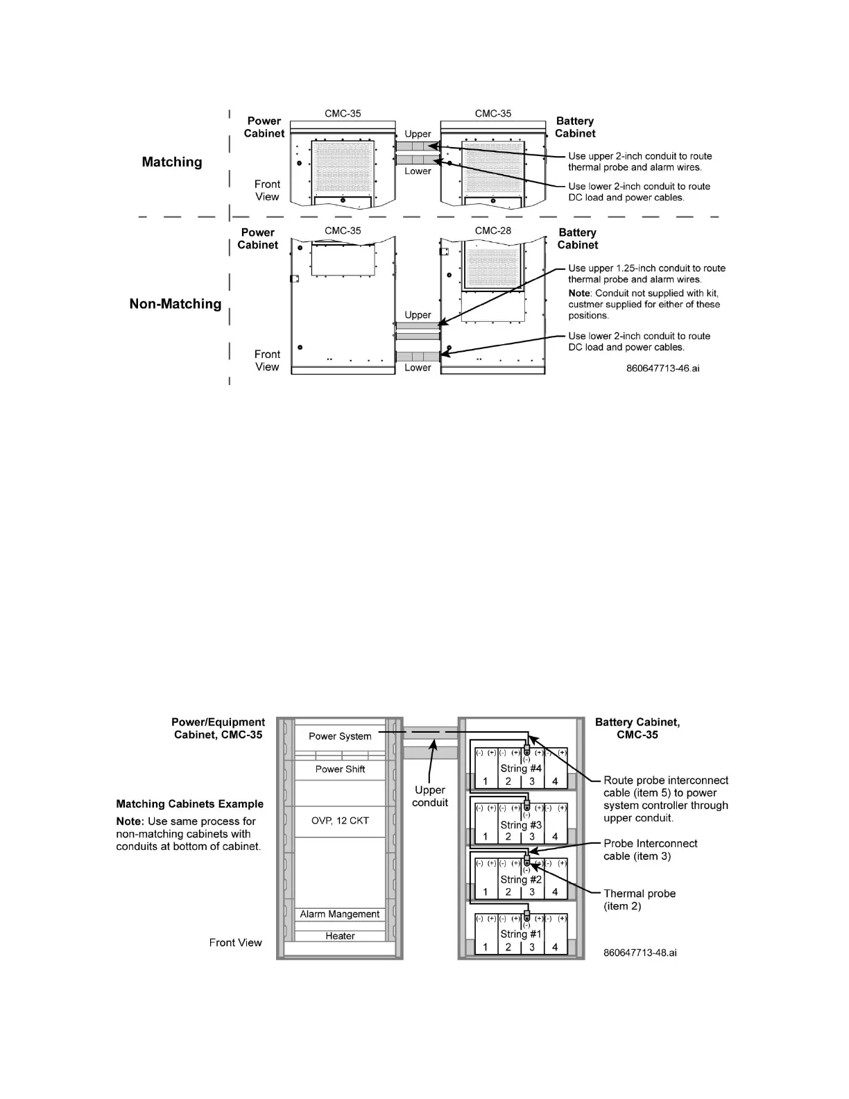
Figure 47. Conduit Locations, CMC Matching and Non-Matching Cabinets
5. Route and connect power and alarm cables from battery cabinet to power cabinet using upper or
lower conduit. All cables are coiled and stored on the top shelf of battery cabinet.
!!– Do Not Use One Conduit For All Cables –!!
■ LED light switch power – lower conduit to power shelf (P/N 860649809, 22 AWG)
■ Door switch alarm – upper conduit to alarm block (P/N 860512789, 22 AWG)
■ High temp alarm – upper conduit to alarm block (P/N 860632173, 22 AWG) – if available
■ Thermosiphon alarm – upper conduit to alarm block (alarm label, 22 AWG) – if available
■ Thermosiphon power – lower conduit to power shelf (DC power label, 18 AWG) – if available
6. Install batteries in cabinet per Section 3, adding thermal probes from kit at time of installation. Refer
to the cabinet SD and also Figure 42.
7. Connect thermal probes and interconnect probe cables (items 2 and 3) to cabinet batteries.
■ For Power/Equipment Cabinet – route item 5 from battery cabinet of topmost thermal probe
through upper conduit to power system controller of power/equipment cabinet, Figure 48.
■ For Power/Battery Cabinet – route item 6 from battery cabinet to bottommost thermal probe on
battery string (string #1) of power/battery cabinet, Figure 49.
Figure 48. Route Interconnect Cable (item 6) to Controller of Power/Equipment Cabinet