Material ID 860647713
Rev B, V.05, February 2022
Page 37
38 Pages
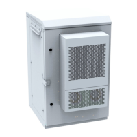
Figure 49. Route Interconnect Cable (item 7) to Bottom String #1 of Power/Battery Cabinet
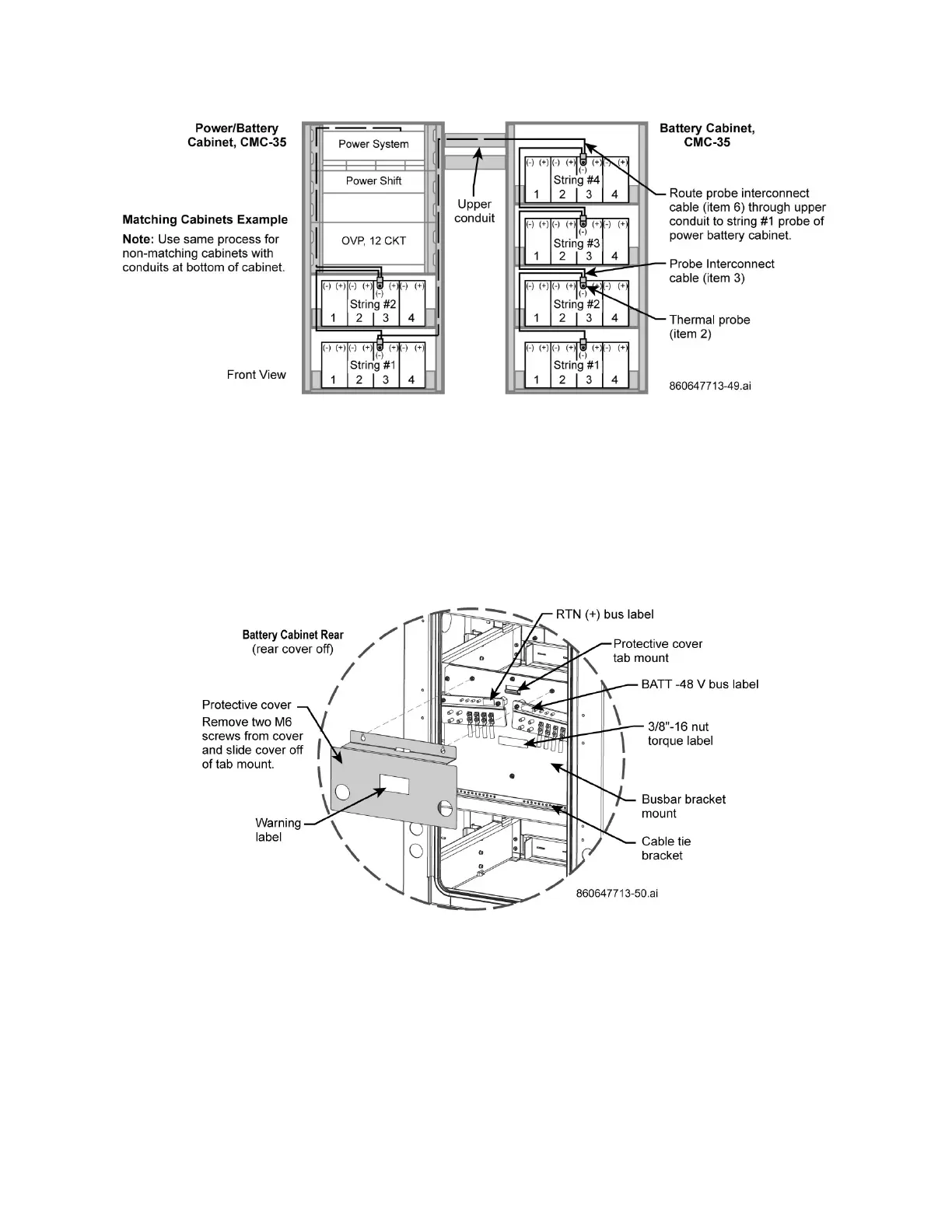
8. Remove master busbar cover, Figure 50.
a. Connect DC load cables (item 8) to busbar and torque lug nuts to 30 FT-LBs, Figure 51.
b. Cable tie the RTN (+) and BATT -48V load (interconnect) cables to the cable bracket below the
busbars and leave enough cable slack to loop cables below the bracket as shown on Figure 51.
c. Route cables through lower conduit to power cabinet; Figure 47, Figure 50, Figure 51.
d. Connect load cables as required to the power shelf on power cabinet.
Note: Leave enough cable slack (loop) from master busbar going to the lower conduit – do not
pull cables tight, Figure 47, Figure 50, Figure 51.
Figure 50. Master Busbar Cover Removal, RTN (+) and -48 V Busbar Locations, Cabinet Rear