4. Design and functioning
21
4.3 Oil circuit
The oil flows from the pressure reservoir (- 6 - Fig. 3)
into the oil thermostat (- 17 - Fig. 3). With oil tempera-
tures < 55 °C/131 °F the oil flows via the by-pass of the
oil cooler directly into the oil filter (- 11 - Fig. 3) and is
then injected into the screw compressor (- 4 - Fig. 3).
With oil temperatures of between 55 °C/131 °F and
70 °C/ 158 °F the oil flow is divided and fed into the oil
cooler (- 12 - Fig. 3) and the by-pass.
With oil temperatures above 70 °C/158 °F the entire oil
flow is directed via the oil cooler through the oil filter into
the screw compressor.
The oil separated by the oil separator element
(- 7 - Fig. 3) is fed through an oil scavage line to the
screw compressor.
The entire oil circulation is based on a differential
pressure in the system. Considering the pressure
difference of approx. 2 bar/29 PSI within the oil circuit,
the oil is then injected into the screw compressor with
approx. 8 bar/116 PSI at a reservoir pressure of e.g.
10 bar/145 PSI.
When the screw compressor is in the off-load mode, a
sufficiently high pressure differential and thus the
required oil injection quantity is achieved owing to the
fact that when the intake regulator (- 2 - Fig. 3) is
closed, a vacuum pressure occurs in the intake
connection.
Excess pressure of approx. 1.5 - 2 bar/22 - 29 PSI
(residual pressure) is produced in the pressure
reservoir at the same time.
4.4 Air circuit
The intake air passes through the intake filter (- 1 - Fig. 3)
and the intake regulator (- 2 - Fig. 3) into the screw
compressor (- 4 - Fig. 3). During the compression
process, the intake air is cooled via the injected oil, and
the developed air/oil mixture flows tangentially into the
pressure reservoir (oil reservoir) (- 6 - Fig. 3). After pre-
separation and subsequent fine separation by the
separator element (- 7 - Fig. 3), the compressed air with
a low oil content is fed via the minimum pressure valve
(- 15 - Fig. 3) and the air cooler (- 16 - Fig. 3) into the
consumer network.
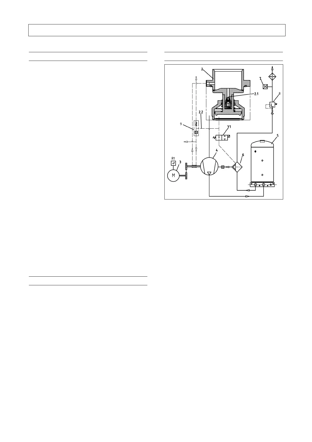
4.5 System control
Fig. 4
4.5.1 System control L07-L11 / L07FS-L11FS
Standstill of the system
• When the system is at rest the intake regulator
(- 2 - Fig. 4) is closed.
• The solenoid valve (Y1 Fig. 4) is de-energised.
• The pressure reservoir (- 5 - Fig. 4) is bled via the
blow-off line (- 2.2 - Fig. 4) and the orifice (-9 - Fig. 4)
into the suction channel.
Starting the system
• The motor (- 3 - Fig. 4) starts up in the Y-mode.
• The compressor extracts a certain volume of air via
a start valve (- 2.1 - Fig. 4). Pressure builds up in
the reservoir and closes the regulator.
• When changing over to Δ operation, the solenoid
valve (- Y1 - Fig. 4) is energised, which blocks the
connection between pressure vessel and intake
regulator.
• The intake regulator opens due to the intake
vacuum pressure. Venting of the control piston
takes place via the blow-off line (- 2.2 - Fig. 4).
• The minimum pressure valve (- 8 - Fig. 4) opens
when the pressure reservoir is approx. 4.5 bar.
• Compressed air is now delivered into the consumer
network.