6. Preparations for commissioning
31
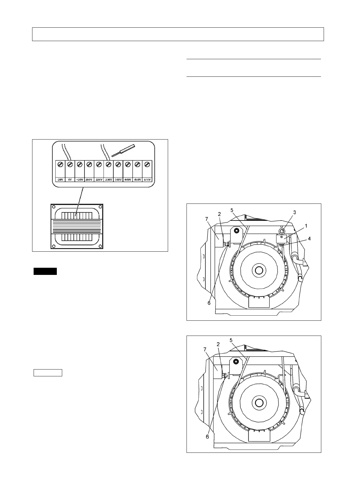
Checking the setting of the control-power
transformer
The control-power transformer is factory-preset to the
rated voltage. However, practice has shown that the
actual supply voltage often differs from this value. In
order to adjust the unit to the local conditions, the
setting of the control-power transformer must be
checked by measuring the control-power transformer
output voltages during under load operation and, if
required, re-set. Several tapping points are provided for
this purpose (see circuit diagram).
Fig. 11
Danger
When carrying out adjustment work on the control-
power transformer, the unit must be electrically
isolated and locked off.
Work on the control cabinet may only be carried
out by electrotechnical specialist personnel.
Only L07RS-L11RS and L07RS FS-L11RS FS:
Danger of electric shock from loaded condensers!
Please always first disconnect the system from the
power supply and wait another 10 minutes before
touching the electrical components. The power
condensers require this time in order to discharge!
Important
A wrong setting of the control-power transformer
jeopardizes the trouble-free operation of
compressor units and can result in malfunction or
damage.
The verification of the control-power transformer
setting is a must during commissioning and
periodic inspection/maintenance, as the voltage
supply conditions may vary.
The correct setting should be checked during
under load operation of the unit by measuring the
control power transformer output voltages.
6.4 Electric motor fasteners for secure
transportation
Fasteners used for securing the electric motor (-1- Fig. 12)
during transportation must be removed prior to
commissioning.
To remove the fasteners, proceed as follows:
• After the panel has been removed, support the motor
by screwing the belt adjusting bolt (-6- Fig. 12)
counterclockwise.
• Loosen the fastening screws (- 3 - and - 4 - Fig. 12)
and remove the fasteners
• Check V-belt (- 5 - Fig. 12) is correctly placed in the
in V-belt pulleys
• Screw the belt adjusting bolt back until it reaches
the lock nut (-2- Fig. 13). Tighten lock nut on holder.
(-7- Fig. 13).
Fig. 12
Fig. 13