6. Preparations for commissioning
27
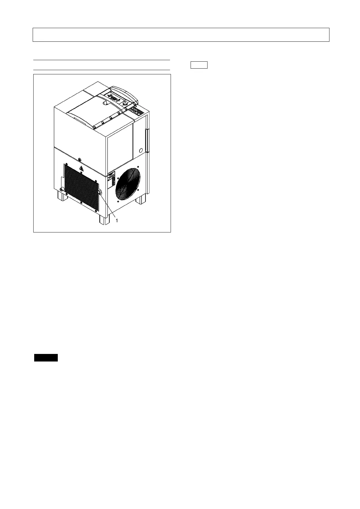
6.2 Compressed air connection
Fig. 9
1 Compressed air connection
The compressed air line system is connected at the
compressed air supply of the screw compressor
( - 1 - Fig. 9).
The AirStation L07(RS) FS-L11(RS) FS series is
connected to the pressure reservoir (-12- Fig. 2b).
For this you should use a flexible connection
(e.g. compressed air hose, compensator).
L07(RS)-L11(RS):
sleeve G 3/4“ (3/4“ NPT)
AirStation L07(RS) FS-L11(RS) FS:
sleeve G 3/4“ (3/4” NPT)
Danger
When connecting the compressor on the mains
side to the compressed air system available at the
customer‘s end, check the operating temperatures
and operating pressures required and examine the
required connecting flange or the connection
thread for proper type, size and functioning
(see Fig. 9).
In the case of connections by means of connecting
hoses, take appropriate measures to prevent
whipping of the loose end in the event that the
hose connection tears off.
Note
After-coolers, separators, collecting reservoirs and the
compressed air lines must be equipped with drain
facilities at their lowest points to drain collected liquids.
These facilities have to be fitted to allow the observance
of the draining of such liquids.
Hand-operated drain facilities have to be actuated in
accordance with the operating instructions.
Automatic drain facilities have to be checked for proper
function at regular intervals. When draining
condensates into a collecting line, which also collects
the condensate from other machines, make sure that
the collecting line is free from back pressure at all lines.
Condensate may contain oil! When draining
condensate, observe the corresponding regulations for
waste water disposal.