EasyManua.ls Logo

Compur Monitors Statox 503 - Page 13

Compur Monitors Statox 503
46 pages
Print Icon
To Next Page IconTo Next Page
To Previous Page IconTo Previous Page
Loading...
Statox 503 Control Module
Issue 10 / 2018 Page 13 of 46
Terminal
Contact
Function
1
Extern
al
Reset
Remote Reset
2
GND (Extern
al
Reset)
3
0
2
2
mA
analog output
Analog output
(must be short – circuited if not in use)
4
GND (0
-
2
2
mA
output
)
*
5
Bridge supply
-
Sensor
head
power supply
*
6
Bridge
Sense
-
Negative
s
ense
-
lead
for
5 wire operation
*
7
Bridge supply 19 ± 1 VDC
Sensor
head
power supply
**
Sensor head power supply with
out
repeater
*
8
Bridge
Sense +
Positive Sense
-
lead for 5 wire operation
*
9
Bridge
center
Sensor
Signal
(mV)
**
10
0
2
2
mA
Current input
Sensor Head Transmitter
S
ignal (mA)
11
Statox 560 ST Trigger
Remote Trigger for selftest
(R +
)
**
12
GND
0 V Sensor Head (Transmitter)
13
24 V
Power supply
Power supply
+ 24 V DC
14
Relay
SF NC
System
failure
relay
-
break contact
15
Relay
SF NO
System failure
relay
-
make contact
16
Relay
SF C
System failure
relay
-
central contact
17
GND
Power supply negative
18
Relay
A2 NC
Alarm
relay
2
break contact
19
Relay
A2 NO
Alarm
relay
2
make
contact
20
Relay
A2 C
Alarm
relay
2
central contact
**
21
24
± 1
V Voltage output
S
ensor head
power supply
with repeater
22
Relay
A1 NC
Alarm
relay
1
break contact
23
Relay
A1 NO
Alarm
relay
1
make contact
24
Relay
A1 C
Alarm
relay
1
central contact
* Sensor heads type
- Statox 501 HRC
- Statox 501 ARE
- Statox 501 LCIR and CO
2
- Statox 501 MCIR
- Statox 501 PID
** Sensor heads type:
- Statox 501/S
- Statox 501 Infratox
- Statox 505
- Statox 506
- Statox 560
Detailed connection
advice in chapter 9 and in
the manuals of the
different sensor heads.
Figure
7
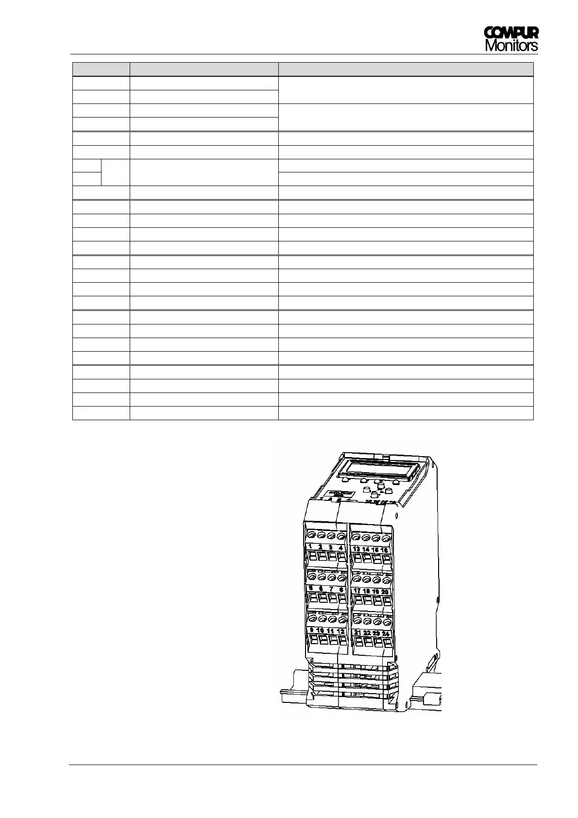
: Pluggable terminal blocks with terminal numbers