Statox 503 Control Module
Page 38 of 46 Issue 10 / 2018
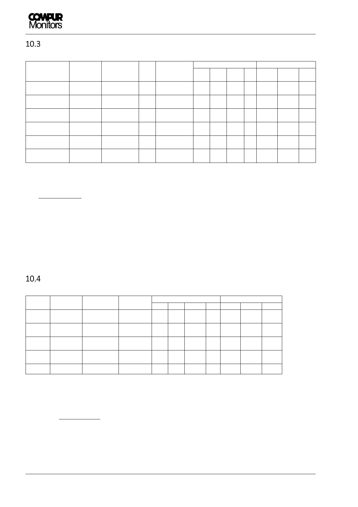
Control Module - Status diagram
Input from Sensor
or transmitter
System
Status
Current
output
Bus
signal
Display
LEDs Relays
A1 A2 S ON
A1
1)
A2
1)
SF
4-20 mA or
bridge voltage
Normal 4 – 20 mA --- Measuring value
OFF OFF OFF ON
active active active
4-20 mA or
bridge voltage
Alarm 1 4 - 20 mA A1 Measuring value
ON OFF
2)
OFF ON
passive
active
2)
active
4-20 mA or
bridge voltage
Alarm 2 4 - 20 mA A2 Measuring value
OFF
2)
ON OFF ON
active
2)
passive
active
22 mA or
mV over range
Over Range 22 mA
2)
Full scale
flashing
2) 2)
OFF ON
2) 2)
active
0 mA or
Error status
System failure
0 mA SF Error code OFF OFF ON ON
active active passive
2 mA or
Service Mode
Service
Mode
3)
2 mA
1)
---
SERVICE MODE
or menu
OFF OFF flashing
ON
active active active
1) Ex-works setting, can be changed by user.
2) Depending on actual alarm status.
3) Priority ranking: Service Mode > SF > (A1 / A2 / Over range)
Common Alarm Module - Status diagram
Bus
input
System
status
Current
output
Display
LEDs
4)
Relays
4)
A1 A2 S ON A1
1)
A2
1)
SF
---
Normal 4 mA
COMMON
OK
OFF OFF OFF ON active active active
A1
Alarm 1 12 mA
COMMON
ALARM 1
ON OFF OFF ON passive
active active
A2
Alarm 2 16 mA
COMMON
ALARM 2
OFF ON OFF ON active passive
active
SF
System
failure
0 mA
COMMON
FAILURE
OFF OFF ON ON active active passive
---
Service
4)
2 mA
1)
Menu OFF OFF flashing
ON active active active
1) Ex-works setting, can be changed by user.
4) The listed LED and relay status describes an isolated alarm event. In case of multiple alarm events
combinations are possible.
The priority ranking for display and current output is: Service Mode > A2 > A1 > SF