Statox 503 Control Module
Page 12 of 46 Issue 10 / 2018
Communication bus
The bus interfaces the 24 V-power supply and the alarm signals from one module to the next.
A Common Alarm Module can evaluate the alarm signals.
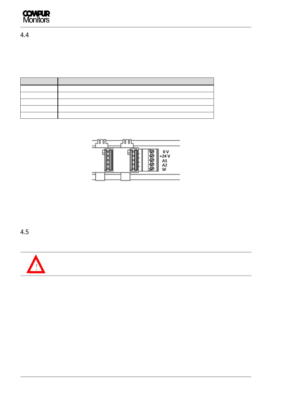
Bus ports Description
ts the signal on terminal A1 to
s the signal on terminal A2 to
A system failure sets the signal on terminal SF to
Figure 6: Bus terminals
Electrical connections
The Statox 503 operates at 24 ± 2 VDC. Higher voltage or short circuits on the terminals
may destroy the module.
The terminals are pluggable. To remove the terminal blocks, set the screwdriver directly over the screws and
press the block to the front side.
The terminals can take cable diameters up to 2.5 mm
2
.