Statox 503 Control Module
Issue 10 / 2018 Page 17 of 46
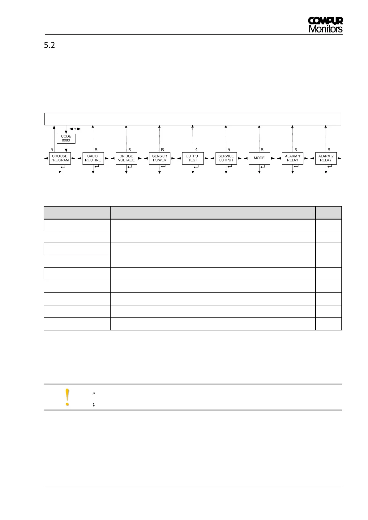
Main menu structure
After pushing ◄- and ► -button together for 2 s and entering the password, you have access to the main
menu. It is structured as a ring with 9 different submenus in which you can set parameters or perform a
calibration. See Figure . Pushing the Reset–button always brings you back into the measuring mode.
Figure 12: Main menu structure
Submenu
Description Chapt.
CHOOSE PROGRAM
1)
Selecting the appropriate program for the relevant sensor head 6.1
CALIB. ROUTINE
1) 2)
Calibration with gas 6.2
SENSOR TEST
1) 2)
Display of the bridge signal in % LEL or mV 6.3
SENSOR POWER
1) 2)
Switches sensor power off or on 6.4
OUTPUT TEST Test of the LEDs, relays, alarms and the analog output 8.1
SERVICE OUTPUT Setting of the analog output in the service mode 8.2
MODE Altering the operation mode (Common Alarm Module or Control Module) 8.3
ALARM 1 RELAY Setting Alarm 1 relays parameters 6.5
ALARM 2 RELAY Setting Alarm 2 relays parameters 6.5
1)
no access if the Statox 503 is operated as Common Alarm Module.
2)
no access if a program for the operation of a 4 – 20 mA transmitter is active.
„MENU NOT ACTIVE“ will be shown for 2 s if a menu is not accessible in the actual mode or
program.
!