Statox 503 Control Module
Page 8 of 46 Issue 10 / 2018
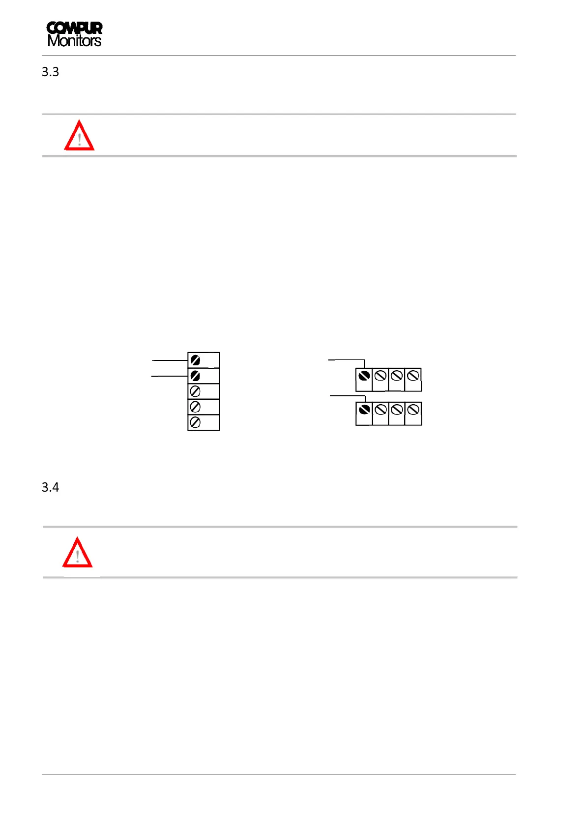
Connecting to power supply
Do not connect the module directly to mains! Do not short circuit terminals! Both can
destroy the module!
There are two options connecting the 24 VDC power supply, see Figure 4.
a) Via bus plug to the communication bus
b) Directly to the relevant Statox 503 Control Module terminal
In both cases all subsequent modules are automatically connected to the power supply via bus. The terminals
are rated to take a max. diameter of 2,5 mm
2
. The module starts operating as soon as it is connected to
power.
Start-up
In any case make sure to select the appropriate program prior to connecting the sensor
head. Otherwise the sensor can be damaged.
Ex works the Statox 503 is configurated to operate as Control Module. After connection to power, it performs
a self-test. It displays the firmware version, then for 5 seconds the actual measuring program, then “PLEASE
WAIT”. The module remains in the system fail mode until the measuring mode has successfully been
activated. During this process the red LED “S” is on.
If no sensor head is connected, an error message is generated (ERROR 2 or ERROR 5, depending on measuring
program). In this case activate the appropriate program as described in chapter 6.1. Then connect the sensor
head as described in chapter 9.
!
+24 VDC
0 V
0 V
+24 VDC
: Connecting the power supply
!