Statox 503 Control Module
Issue 10 / 2018 Page 29 of 46
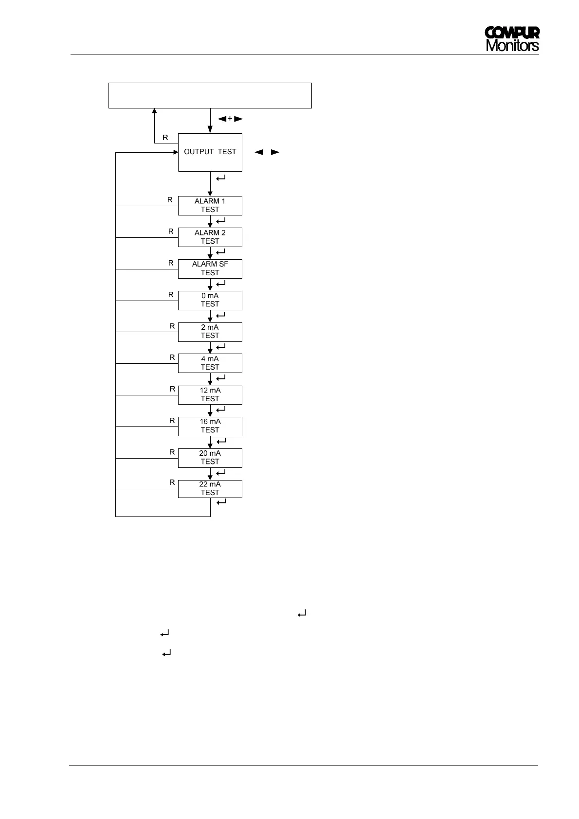
Figure 20: Diagram functional test
1. Enter the menu „OUTPUT TEST“ by pushing .
2. Always push to continue with the next submenu.
3. With the last you will return to the main menu.
4. Push RESET to return to the measuring mode.
LED A1 flashes, Relay A1 switches
LED A2 flashes, Relay A2 switches, alarm report A2 to bus
LED S flashes, Relay SF switches, alarm
22 mA between Pin 3 and 4
.
.
.
.
.
.
.