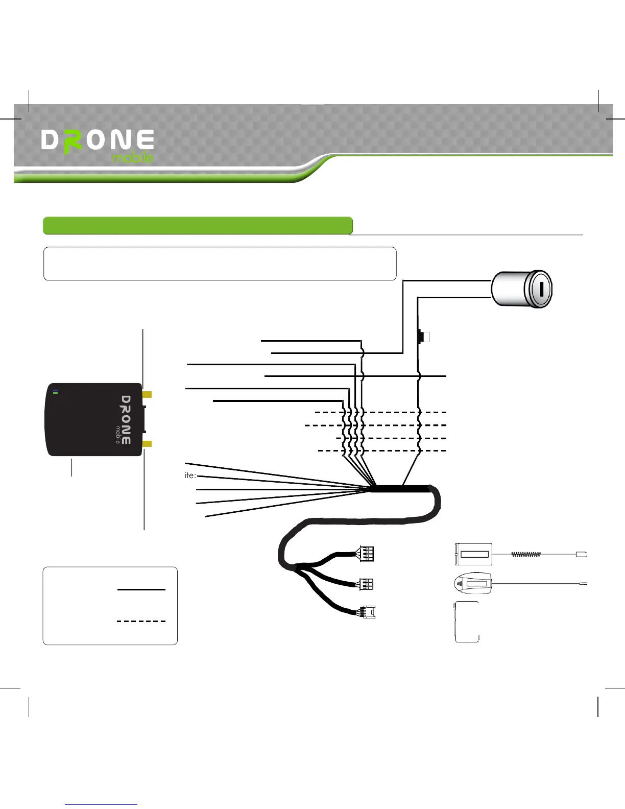
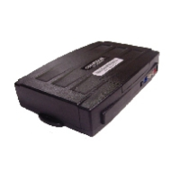
Wiring Diagrams
DroneMobile can be installed using installation Type 1-Standalone, Type 2-Data, and Type 3-Hardwire
Required
Optional
Follow Type 1 when using DroneMobile as a standalone system
with a Firstech RF Kit and GPS tracking device
Copyright 2011 Firstech, LLC. | 4
Type 1 - Standalone With RF Kit and Bypass
Red: (+) 12 Volt Constant
Yellow:
White:
Blue/Black: (-) Programmable Output 1
Brown: (-) Programmable Alarm Trigger Input
Green: (+) Ignition Input
Black: (-) Ground Input
Blue(Thin)
Blue: (-) Programmable Output 2
Orange: (-) Programmable Output 3
Optional External Cellular Antenna Port
Optional External GPS Antenna Port
Yellow:
White:
Black:
Black:
Orange:
Reset Button
6 Pin Antenna Port
RS232 Data Port
4 Pin Antenna Port
12V+ Constant
12V+ Ignition
Chassis Ground
See Option 2-05
See Special Option Group 2
Bypass Module
TM
Do Not Use Both Antenna
Ports At The Same Time
See Special Option Group 2
See Special Option Group 2
DR-2000 Install Guide