14 Installation
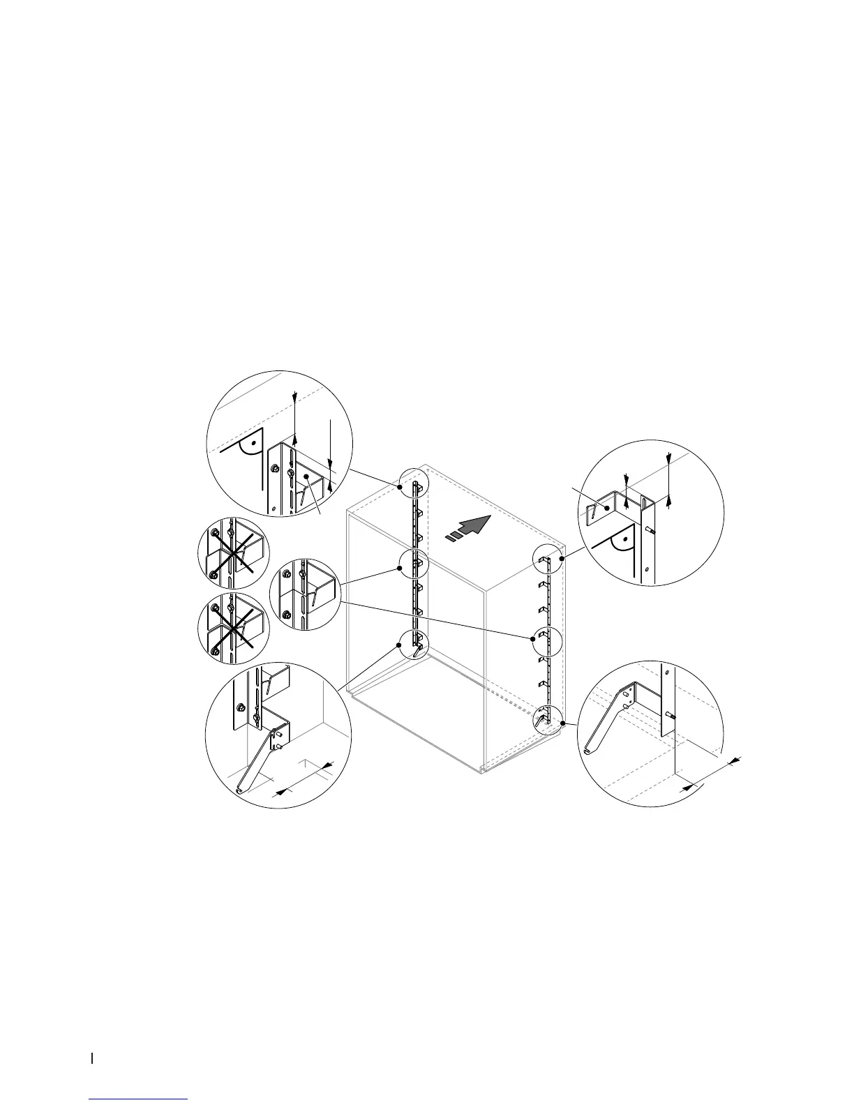
2. Mount the lateral supports of the post-evaporation unit to the duct walls:
• Align the lateral supports with the “TOP” labeled mounting bracket on top with an identical dis-
tance to the duct ceiling (target measure ”a”: 65 mm, admissible range: 0...90 mm) and with
a distance “b” of 100 mm to the intersection of the AHU, then x them via the topmost fastening
hole to the duct wall using a self-tapping screw 6.3 x 25 mm (do not tighten the screw yet).
Important: to be able to mount the optional booster the distance of 100 mm to the intersection
of the AHU must be maintained.
• Align both supports at right angles to the duct ceiling and check the distance to the duct ceiling
once more (the distance must be identical for both supports). Then, x both supports approx.
every 30 cm with a self-tapping screw 6.3 x 25 mm to the duct walls.
Note: evenly allocate the self-tapping screws over the entire length of the supports.
• This step must be carried out only on ducts with a height >2100 mm where the supports consist
of several proles: x the additional supports ush and in line with the upper support approx.
every 30 cm with self-tapping screws 6.3 x 25 mm to the duct walls.
Note: evenly allocate the self-tapping screws over the entire length of the supports.
Abb. 4: Mount the lateral supports
a= target measure 65 mm (admissible range 0...90 mm)
b= min. 100 mm
a
b
a
b
TOP
TOP