MANUALP/4000_SERVICE_0712 July2012
51
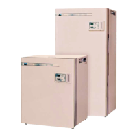
4. Below is the typical ZP22 Interface Controller Board layout showing the
locations of the different ports – sensor, output, display and main power
input.
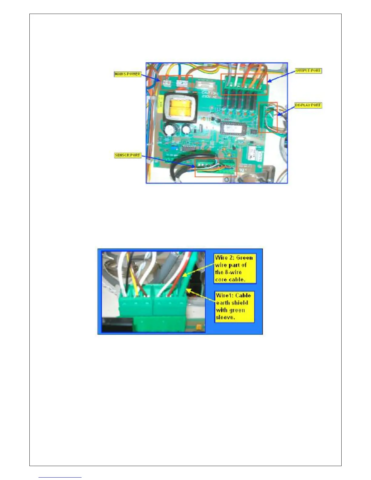
5. On the display port, locate the wires connected on the “GND” position.
The 2 earth wires connected are cable shield and green wire part of the
8-wire core cable.
Wire 1: Cable earth shield with green sleeve.
Wire 2: Green wire part of the 8-wire core cable.