MANUALP/4000_SERVICE_0712 July2012
59
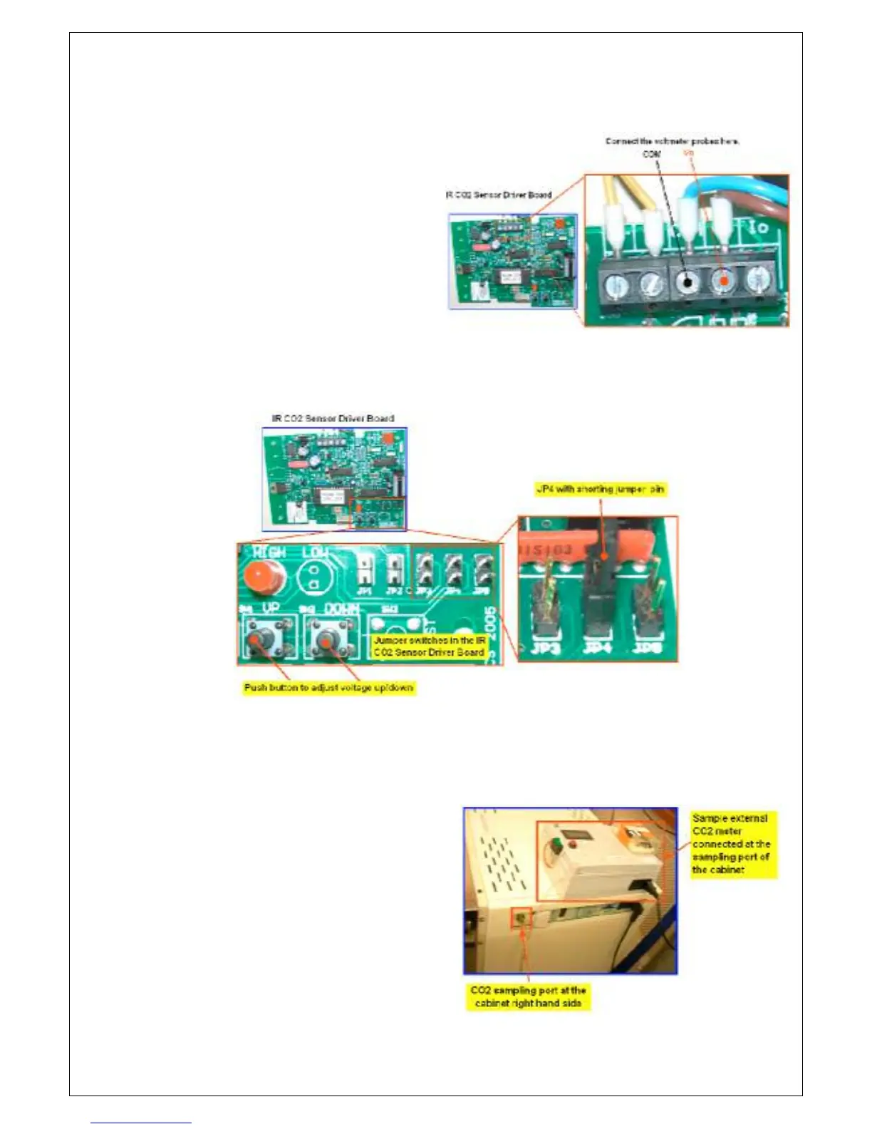
2.6 Perform the IR CO
sensor driver board Zero Offset Calibration. To
adjust the ZERO of the CO
2
display, it is necessary to proceed as follows:
a. Connect a voltmeter to the IR
CO
sensor board output
terminals. This is the terminal
with wire going to the ZP22
interface controller board.
b. With JP5 OPEN (no shorting jumpers inserted), connect the shorting
jumper onto pins of JP4, use the ‘UP’ or ‘DOWN’ buttons on the CO
PCB to adjust the voltmeter to read 0.005 volts DC. (The cabinet
display will read about 0.2% CO
2
).
c. Remove the shorting jumper on JP4 once the voltmeter reads 0.005
volts DC.
2.7 Perform the IR constant or Span calibration. To adjust the SPAN of the
CO
2
display, it is necessary to proceed as follows:
a. Connect the external CO
meter on the sampling port
and take note of the external
CO
meter reading. Compare
this with the cabinet display
and adjust the span as
appropriate.