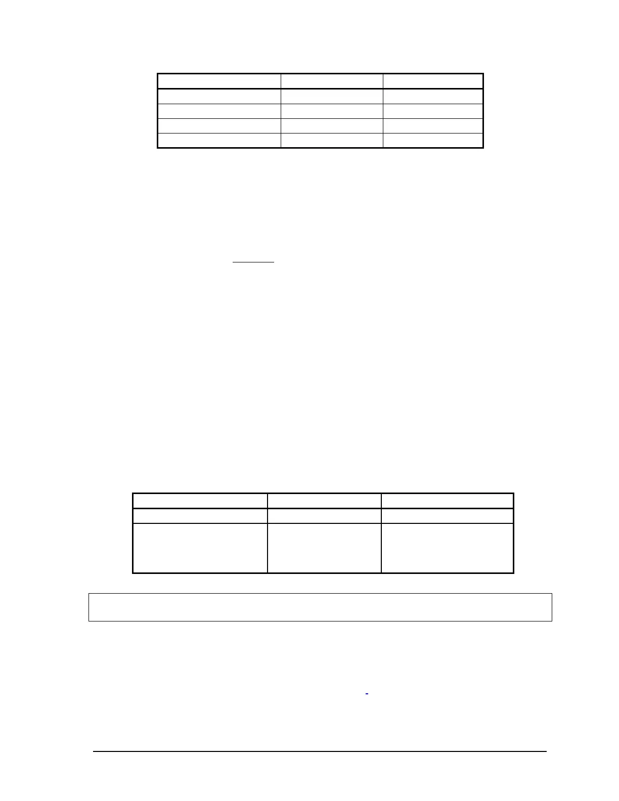
5V Current (mA) 24V Current (mA)
5232 Controller Board
500 0
5601 I/O Module
500 100
Analog Outputs
10 55
Total
1010 155
The 5232 controller board has 1300mA available from the 5V supply. A minimum of 100mA is
available from the 24V supply. Additional current is available from the 24V supply when the 5V is
not loaded to its 1300mA maximum.
The total 24V supply current available is calculated as follows:
24V current = 100 + ((1300 – Total Current @ 5V) x 0.25)
=
172.5mA
where:
100 = Minimum current @ 24V
1300 = Maximum current @ 5V
Total Current @ 5V = Sum of 5V current required for system
0.25 = Derating factor is a constant
In this example, when 1010mA is required at 5V, 172.5mA is available on the 24V supply on
connector P3. This is greater than the 155mA required by the integrated 5601 I/O module. The
Recommended AC Power Supply Configuration can therefore be used to power the SCADAPack P4
controller.
4.2.5.2 SCADAPack P4A
As illustrated in section 4.2.1-Recommended AC Power Supply Configuration the 5232 controller
board may be powering a 5601 I/O module as well as other 5000 Series modules.
The following table shows current requirements of the controller board and the 5601 I/O modules:
5V Current (mA) DC Input Current (mA)
5232 Controller Board
500 0
5604 I/O Module
15 to 170
See specifications for
details.
10 + 12/24V boost
converter requirements.
Can vary up to 550mA.
See Note below.
Note: The DC Input current depends on the actual DC Input voltage, whether the DC Input is
boosted and the load on the output.
4.2.5.2.1 Example 1
In the following example a 5232 Controller board with a 5604 I/O Module and analog outputs is
powered using the Recommended AC Setup
such that 24V will be available across the DC PWR
terminals on connector P3 to power the integrated I/O board.
This 24V power must be available for
both analog outputs and all analog inputs that require power. In this example, both analog outputs
SCADAPack 32 Controller Hardware Manual
May 24, 2006
14