Preparing a VFC400-USB for first use VFC400-USB User Guide 17
Each alarm trigger condition consists of a threshold temperature value, an activation
type (which can be instant, consecutive or accumulative
1
) and a delay time, if it is not an
instant alarm.
If an alarm trigger condition requires readings to exceed an upper threshold temperature
it is called an
upper alarm
. If an alarm trigger condition requires readings to go below a
lower threshold it is called a
lower alarm
.
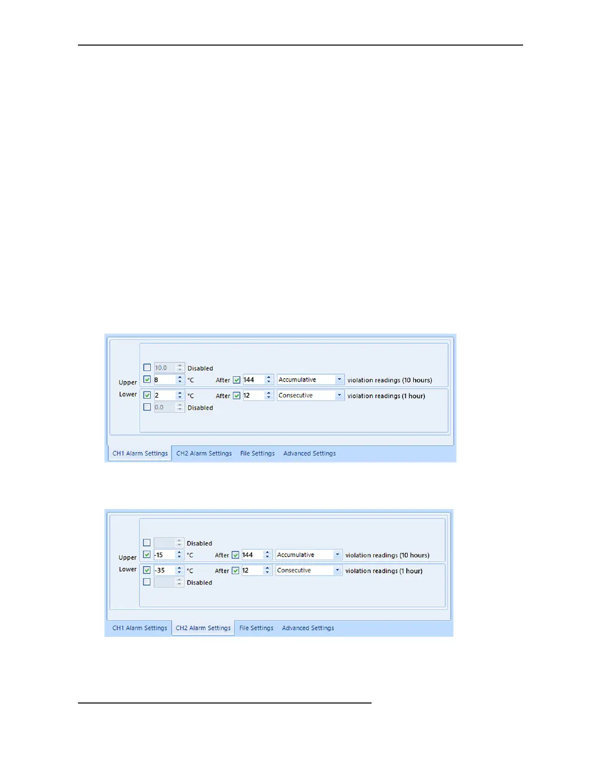
All alarm trigger conditions are entered in the Alarm Settings tab during configuration
of the logger with Control Solutions VTMC. Alarms are configured separately for each
channel. If you have chosen to log only one of the channels, the controls for the other
channel are not available.
The screen shows an example where:
l
the upper primary alarm for channel 1 is triggered when the temperature is 8°C or
above for an accumulative time of 10 hours.
l
the lower primary alarm for channel 1 is triggered when the temperature is 2°C or
below continuously for 1 hour.
Figure 2: Sample Alarm Configuration Settings for channel 1 of a VFC400-USB
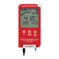
l
The alarm parameters for the second channel can be entered on the next tab.
Figure 3: Sample Alarm Configuration Settings for channel 2
1
l
Instant = one temperature reading is above (below) the threshold
l
Consecutive = temperature readings are above (below) the threshold for the time defined in the activation delay
without interruption
l
Accumulative = temperature readings are above (below) the threshold for the total time defined in the activation delay
time, but may not necessarily be sequential