Safety
Information
Product
Information
Mechanical
Installation
Electrical
Installation
Getting
Started
Menu 0
Running
the motor
Optimisation Macros
Advanced
Parameters
Technical
Data
Diagnostics
UL Listing
Information
Unidrive User Guide 41
Issue Number: 9 www.controltechniques.com
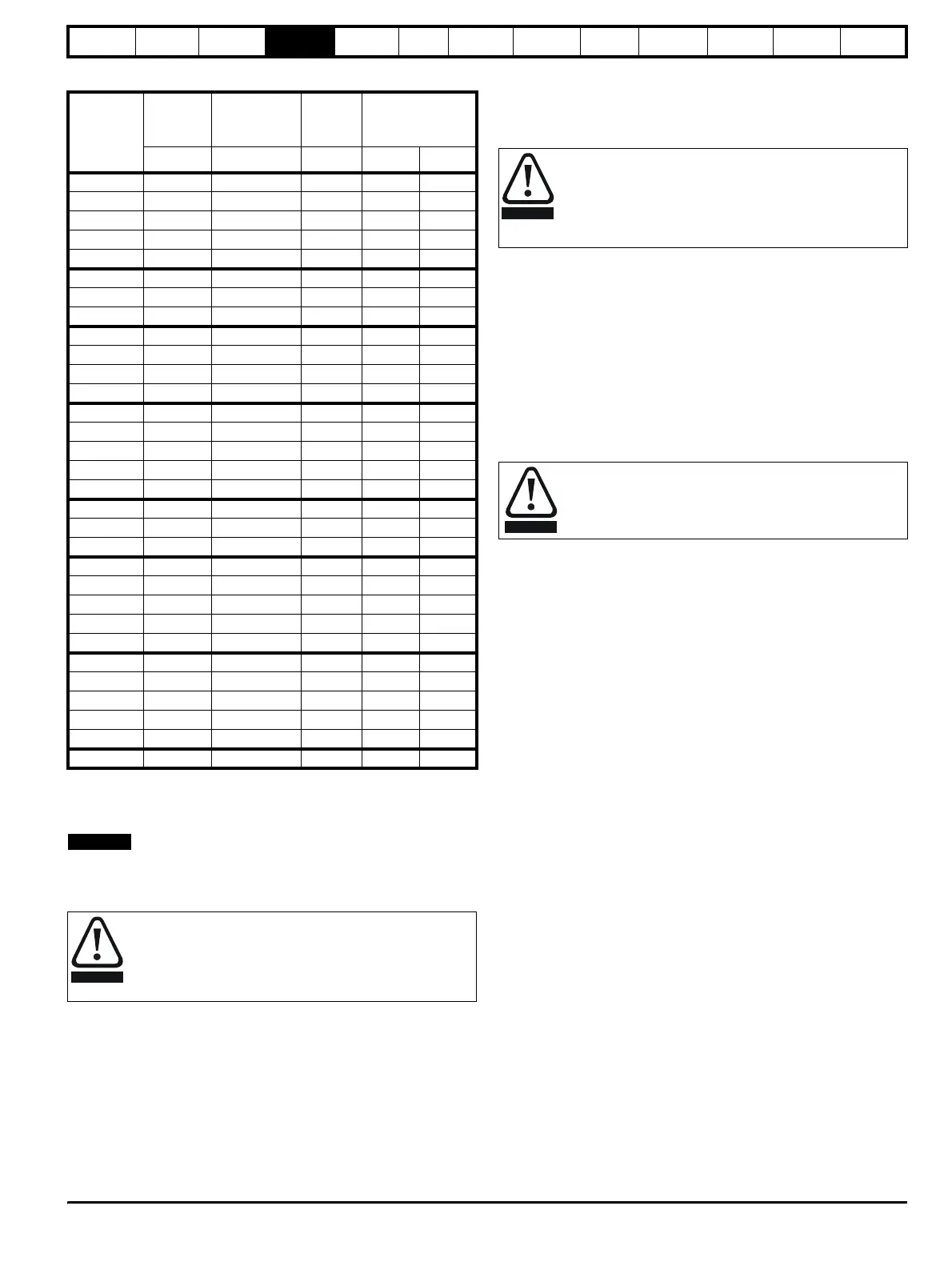
Table 4-1 Input current, fuse and cable size ratings
The recommended cable sizes above are only a guide. Refer to local
wiring regulations for the correct size of cables. In some cases a larger
cable is required to avoid excessive voltage drop.
N
UL listing is dependent on the use of the correct type of UL-listed fuse,
and applies when symmetrical short-circuit current does not exceed 5kA
for sizes 1 to 3, 10 kA for size 4 or 18kA for size 5.
A fuse or other protection must be included in all live connections to the
AC supply.
An MCB (miniature circuit breaker) or MCCB (moulded case circuit
breaker) with type C tripping characteristics and the same rating as the
fuse(s), may be used in place of the fuse(s), on condition that the fault
current clearing capacity is sufficient for the installation.
4.4.3 Fuse Types
The fuse voltage rating must be suitable for the drive supply voltage.
• Europe: Type gG HRC industrial fuses to IEC60269 (BS88)
• USA: Class CC fuses up to 30A, Class J above 30A
4.4.4 Ground connections
The drive must be connected to the system ground of the AC supply.
The ground wiring must conform to local regulations and codes of
practice.
4.4.5 Main AC supply contactor
The recommended AC supply contactor type for all sizes is AC1.
4.5 Output circuit and motor protection
The output circuit has fast-acting electronic short-circuit protection which
limits the fault current to typically no more than five times the rated
output current, and interrupts the current in approximately 20µs. No
additional short-circuit protection devices are required.
The drive provides overload protection for the motor and its cable. For
this to be effective, Pr 0.46 Motor rated current must be set to suit the
motor.
There is also provision for the use of a motor thermistor to prevent
overheating of the motor, e.g. due to loss of cooling.
4.5.1 Cable types and lengths
Since capacitance in the motor cable causes loading on the output of the
drive, ensure the cable length does not exceed the values given in Table
4-2 and Table 4-3.
Use 105°C (221°F) (UL 60/75°C temp rise) PVC-insulated cable with
copper conductors having a suitable voltage rating, for the following
power connections:
• AC supply to external EMC filter (when used)
• AC supply (or external EMC filter) to drive
• Drive to motor
• Drive to braking resistor
Model
Typical
input
current
Maximum
continuous
input current
Fuse
rating
Cable size
AAA
mm
2
AWG
UNI1201 2.4 4.0 6.0 1.5 16
UNI1202 3.5 6.0 10 2.5 14
UNI1203 4.6 8.0 10 2.5 14
UNI1204 6.5 10 10 2.5 14
UNI1205 8.6 12.5 16 2.5 14
UNI2201 10.8 13.9 16 2.5 14
UNI2202 14.3 16.9 20 4 10
UNI2203 19.8 27 35 4 10
UNI3201 26 28 40 6 8
UNI3202 39 43 60 10 6
UNI3203 53 56 70 16 4
UNI3204 78 84 80 25 4
UNI1401 3.0 4.5 6.0 1.5 16
UNI1402 4.3 5.5 10 2.5 14
UNI1403 5.8 6.8 10 2.5 14
UNI1404 8.2 8.6 10 2.5 14
UNI1405 10 12 16 2.5 14
UNI2401 13 16 16 2.5 14
UNI2402 17 20 20 4 10
UNI2403 21 25 35 4 10
UNI3401 27 34 40 6 8
UNI3402 32 39 50 10 6
UNI3403 40 53 60 10 6
UNI3404 52 66 70 16 4
UNI3405 66 82 80 25 4
UNI4401 76 98 100 35 2
UNI4402 91 114 125 35 2
UNI4403 123 152 160 50 0
UNI4404 145 205 200 70 2/0
UNI4405 181 224 250 95 3/0
UNI5401 280 321 450 120 4/0
Fuses
The AC supply to the drive must be fitted with suitable
protection against overload and short-circuits. Table 4-1
shows recommended fuse ratings. Failure to observe this
requirement will cause risk of fire.
NOTE
WARNING
The ground loop impedance must conform to the
requirements of local safety regulations.The drive must be
grounded by a connection capable of carrying the
prospective fault current until the protective device (fuse,
etc.) disconnects the AC supply.The ground connections
must be inspected and tested at appropriate intervals.
Pr 0.46 Motor rated current must be set correctly to avoid a
risk of fire in the event of motor overload.
WARNING
WARNING