Safety
Information
Product
Information
Mechanical
Installation
Electrical
Installation
Getting
Started
Menu 0
Running
the motor
Optimisation Macros
Advanced
Parameters
Technical
Data
Diagnostics
UL Listing
Information
Unidrive User Guide 43
Issue Number: 9 www.controltechniques.com
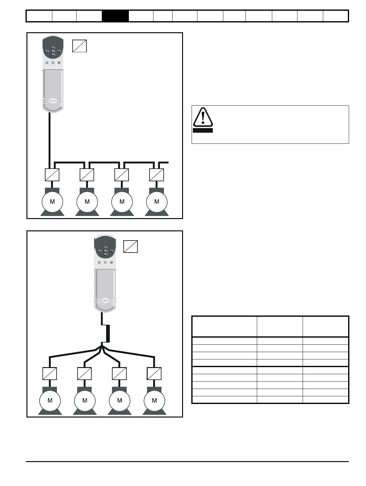
Figure 4-5 Preferred chain connection for multiple motors
Figure 4-6 Alternative connection for multiple motors
4.5.3 Star / delta motor operation
The voltage rating for star and delta connections of the motor should
always be checked before attempting to run the motor.
The default setting of the motor rated voltage parameter is the same as
the drive rated voltage
i.e. 400V drive 400V rated voltage
200V drive 200V rated voltage
A typical 3 phase motor would be connected in star for 400V operation
or delta for 200V operation however variations on this are common
i.e. star 690V delta 400V
Incorrect connection of the windings will lead to severe under or over
fluxing of the motor, leading to a very poor output torque or motor
saturation and over-heating respectively.
4.5.4 Output contactor
A contactor is sometimes required to be fitted between the drive and
motor for safety isolation purposes.
The recommended motor contactor is the AC3 type.
Switching of an output contactor should only occur when the output of
the drive is disabled.
Opening or closing of the contactor with the drive enabled will lead to:
1. OI.AC trips (which cannot be reset for 10 seconds)
2. High levels of RFI noise emission
3. Increased contactor wear and tear
For more information please contact the supplier of the drive.
4.6 Braking
Internal connection does not require the cable to be armoured or
shielded.
In-built in the Unidrive software is overload protection for the brake
resistor. In order to enable and set-up this function, it is necessary to
enter two values into the drive:
• Resistor short-time overload time (Pr 10.30)
• Resistor minimum time between repeated short-time overloads (Pr
10.31)
This data is available from the manufacturer of the braking resistors.
4.6.1 Minimum resistances and power ratings
Table 4-4 Minimum resistance values and peak power rating for
the braking resistor at 40°C (104°F)
The minimum resistance allows the braking resistor to dissipate up to
approximately 150% of the power rating of the drive for up to 60
seconds.
For high-inertia loads or under continuous braking, the continuous power
dissipated in the braking resistor may be as high as the power rating of
the drive. The total energy dissipated in the braking resistor is dependent
on the amount of energy to be extracted from the load.
Motor protection
relay
Chain connection (preferred)
Star connection
Inductor
Motor protection
relay
If the cable between the drive and the motor is to be
interrupted by a contactor or circuit breaker, ensure that the
drive is disabled before the contactor or circuit breaker is
opened or closed. Severe arcing may occur if this circuit is
interrupted with the motor running at high current and low
speed.
Model
Minimum
resistance
Ω
Instantaneous
power rating
kW
UNI1201 to UNI1205 20 15
UNI2201 20 15
UNI2202 to UNI2203 15 20
UNI3201 to UNI3205 5 60
UNI1401 to UNI1405 40 15
UNI2401 40 15
UNI2402 to UNI2403 30 20
UNI3401 to UNI3405 10 60
UNI4401 to UNI4405 5 120
WARNING