Safety
Information
Product
Information
Mechanical
Installation
Electrical
Installation
Getting
Started
Menu 0
Running
the motor
Optimisation Macros
Advanced
Parameters
Technical
Data
Diagnostics
UL Listing
Information
54 Unidrive User Guide
www.controltechniques.com Issue Number: 9
4.9.3 Unidrive VTC control terminal default
configuration
The following is a list of the terminal default functions for Unidrive VTC.
Any terminal not listed has the same default function as Unidrive.
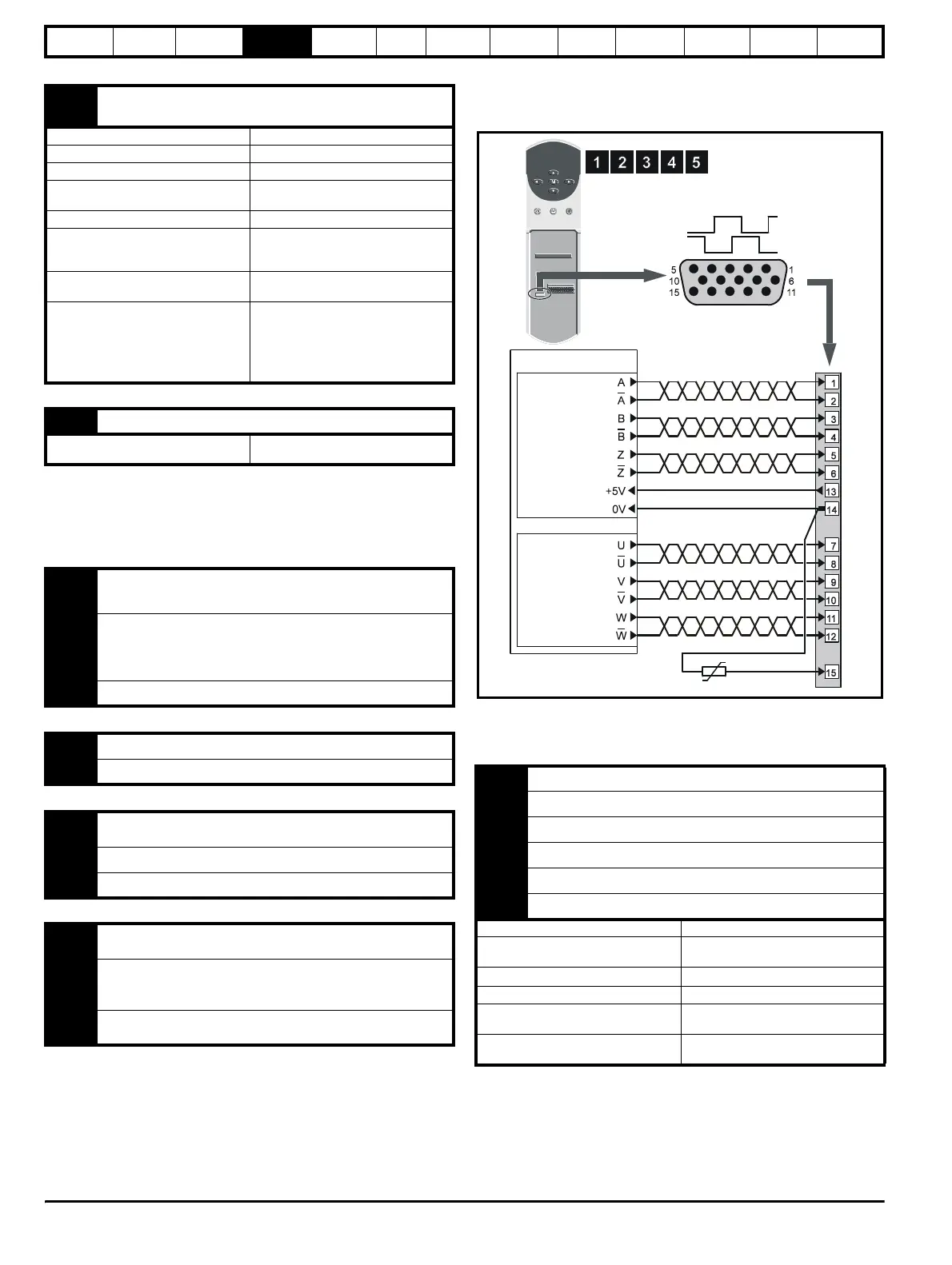
4.10 Encoder connections
4.10.1 Quadrature encoder connections
Figure 4-17 Encoder connections (default configurations)
For encoder cable screening, see section 4-10 Feedback cable, twisted
pair on page 47.
Descriptions of the encoder connections
30 Drive enable input F7
OL> EXTERNAL TRIP INPUT
CL> DRIVE ENABLE input
Type Negative or positive logic digital inputs
Logic mode controlled by... Parameter
8.27
Voltage range 0V to +24V
Absolute maximum
voltage range
–3V to +30V
Input current when 0V applied ≥3.2mA
Negative-logic levels
Inactive state (input open-circuit):
>+15V
Active state: <+5V
Positive-logic levels
Inactive state (input open-circuit): <+5V
Active state: >+15V
Sample period
Enable function
PWM switching frequency dependent
5.5ms for 3, 6, & 12kHz
7.4ms for 4.5 & 9kHz
Disable or trip function
1ms
31 0V common (digital)
Function
Common connection for external digital
devices.
5 Analog input 1
±10V frequency reference input
6 (differential input)
7 Analog input 2
EUR> ±10V frequency reference
input
USA> 4 to 20 mA frequency
reference input
8 Analog input 3 Motor thermistor input (PTC)
9 Analog output 1 Frequency output
10 Analog output 2 Total motor current output
24 Digital input / Output F1
EUR> AT SPEED output
USA> DRIVE RUNNING output
25 Digital input / Output F2 RESET input
26 Digital input / Output F3 PRESET SELECT
27 Digital input F4
EUR> RUN FORWARD input
USA> RUN input
28 Digital input F5
EUR> RUN FORWARD input
USA> ANALOG INPUT 1 / INPUT
2 SELECT input
29 Digital input F6
ANALOG INPUT / PRESET REF
SELECT input
1 Quadrature channel A
2 Quadrature channel A\
3 Quadrature channel B
4 Quadrature channel B\
5 Marker pulse channel Z
6 Marker pulse channel Z\
Type EIA422 differential receivers
Maximum data rate
250kHz (equivalent of 3,000rpm with a
5,000 lines per revolution encoder)
Line termination components
120
Ω (switchable using Pr 3.24)
Line loading 1 unit load
Absolute maximum applied voltage
relative to 0V
±15V
Absolute maximum applied differential
voltage
±25V
Encoder connector
Female 15-way D-type
Encoder
Commutation
signal
connections for
servo-encoders
only
Incremental
signal
connections for
all encoders