Safety
Information
Product
Information
Mechanical
Installation
Electrical
Installation
Getting
Started
Menu 0
Running
the motor
Optimisation Macros
Advanced
Parameters
Technical
Data
Diagnostics
UL Listing
Information
16 Unidrive User Guide
www.controltechniques.com Issue Number: 9
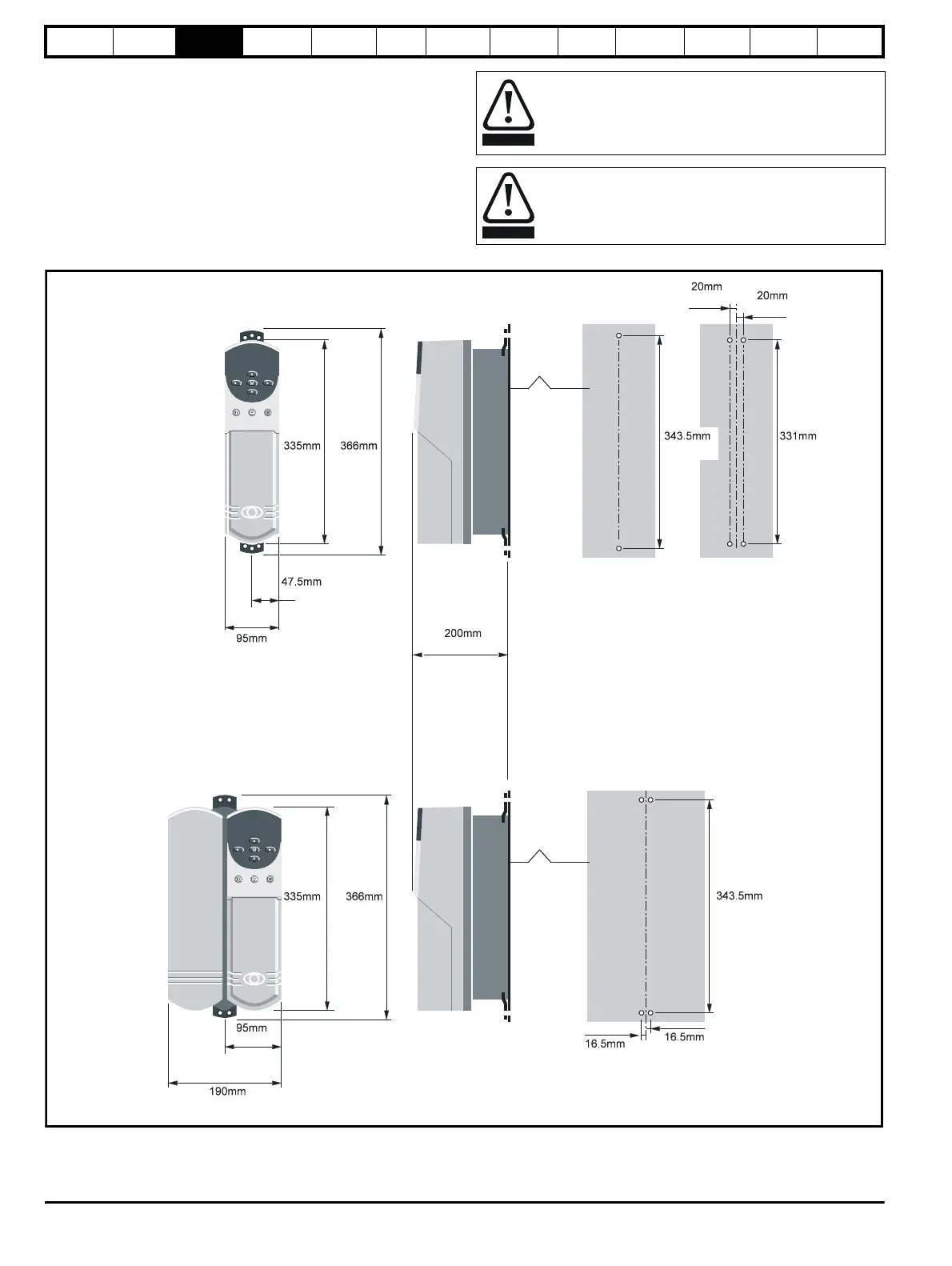
3.6 Mounting methods
Unidrive sizes 1 to 4 can be either through hole or surface mounted
using the appropriate brackets.
The Unidrive size 5 consists of two modules:
• the control module should be surface mounted
• the power module must be through hole mounted.
The following drawings show the dimensions of the drive and mounting
holes for each method to allow a back plate to be prepared.
Lifting the drive
The weights of model sizes 3 and 4 are 22kg (49lbs) and
70kg (154lbs) respectively; the size 5 power module exceeds
100kg (220lbs). Use appropriate safeguards when lifting
these models.
If the drive has been used at high load levels for a period of
time, the heatsink may be hot. Human contact with the
heatsink should be restricted.
WARNING
WARNING
Model
size 1
Model
size 2
Back-plate
Back-plate
0.787in
0.787in
13.524in
13.031i
13.189in 14.409in
1.870in
3.740in
7.874in
13.189in 14.409in
3.740in
7.480in
0.650in
0.650in
13.524in
Figure 3-6 Surface mounting of model sizes 1 and 2