Safety
Information
Product
Information
Mechanical
Installation
Electrical
Installation
Getting
Started
Menu 0
Running
the motor
Optimisation Macros
Advanced
Parameters
Technical
Data
Diagnostics
UL Listing
Information
74 Unidrive User Guide
www.controltechniques.com Issue Number: 9
See Figure 6-3.
Excessive values of Pr 0.08 can cause the motor to be overheated.
Closed-loop
Pr 0.08 (Pr 3.11) operates in the feed-forward path of the speed-control
loop in the drive. See Chapter 8 Optimisation .
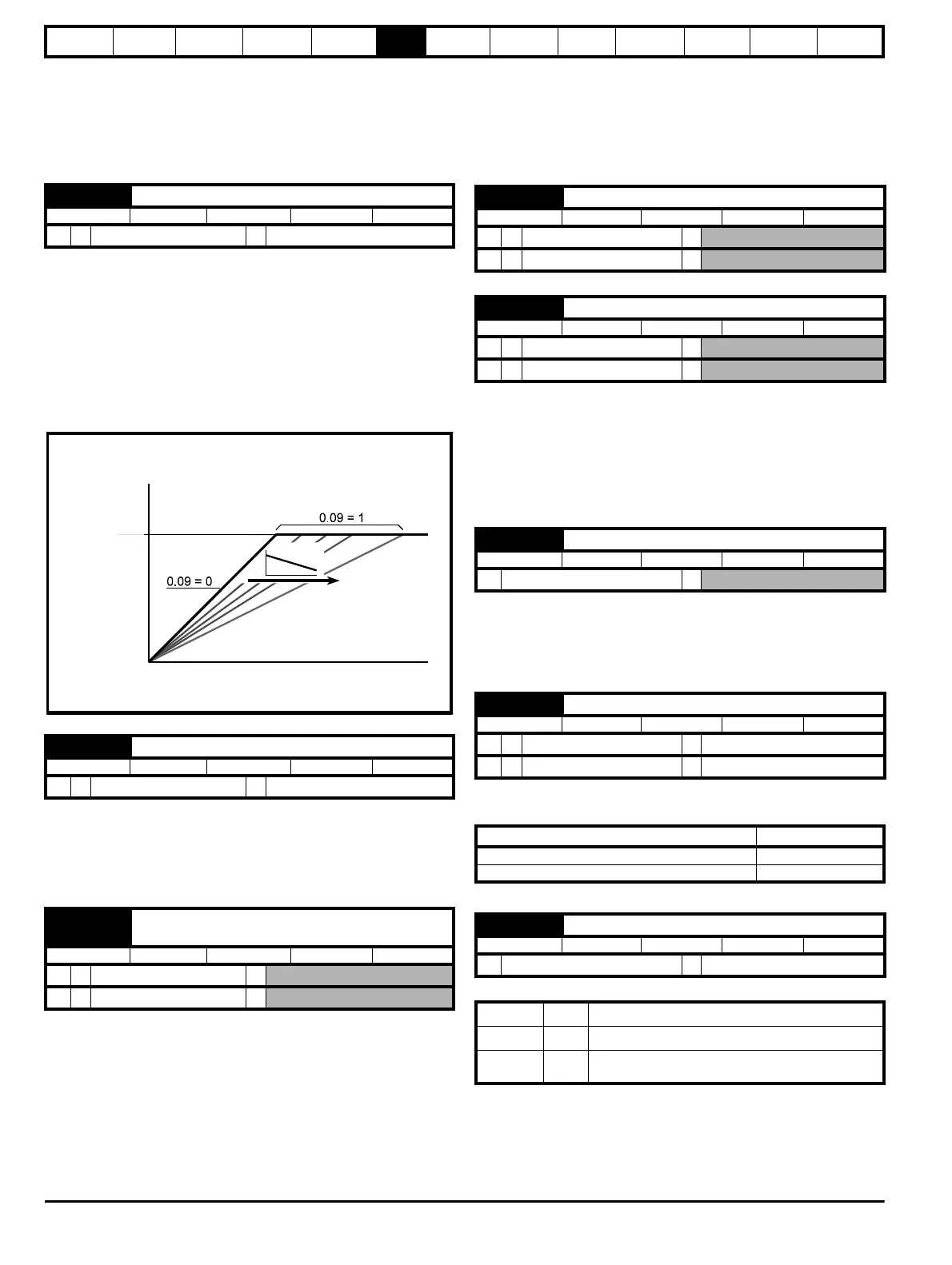
Open-loop
Set Pr 0.09 (Pr 5.13) at 0 when the V/f characteristic applied to the motor
is to be fixed. It is then based on the rated voltage and frequency of the
motor.
Set Pr 0.09 at 1 when reduced power dissipation is required in the motor
when it is lightly loaded. The V/f characteristic is then variable resulting
in the motor voltage being proportionally reduced for lower motor
currents. Figure 6-4 shows the change in V/f slope when the motor
current is reduced.
Figure 6-4 Fixed and variable V/f characteristics
Closed-loop
Pr 0.09 (Pr 3.12) operates in the feedback path of the speed-control loop
in the drive. See Chapter 8 Optimisation .
6.2.5 Monitoring
Open-loop
Pr 0.10 (Pr 5.04) indicates the value of motor speed that is estimated
from the following:
Pr 0.12 Post-ramp frequency reference
Pr 0.42 Motor - no. of poles
The value of Pr 0.10 is applied to the analog output on terminal 9 to
indicate estimated speed.
Closed-loop
Pr 0.10 (Pr 3.02) indicates the value of motor speed that is obtained from
the speed feedback.
The value of Pr 0.10 is applied to the analog output on terminal 9 to
indicate speed.
When the frequency/speed is constant, [Pr 0.12] = [Pr 0.11]. During
acceleration and deceleration, the two values may differ.
OL> [Pr 0.12] differs from [Pr 0.11] also under either of the following
conditions:
• When the drive is in current limit
• During braking in a standard ramp mode (Pr 0.15 Ramp mode
selector set at Stnd.Hd or Std.Ct).
When the motor is being driven below its rated speed, the torque is
proportional to [Pr 0.13].
6.2.6 Jog reference, Ramp mode selector, Stop and
torque mode selectors
Enter the required value of jog frequency/speed.
The frequency/speed limits affect the drive when jogging as follows:
Select the required ramp mode as follows:
For more information, see Pr 2.04 in section 10.22 Advanced
Features on page 182.
0.09 {5.13} Dynamic V/f select
RW Bit
OL
Ú
0 or 1
Ö
0
0.09 {3.12} Speed control D gain
RW Uni
CL
Ú
0 to 32,000
Ö
0
0.10 {5.04}
0.10 {3.02}
OL> Estimated motor speed
CL> Motor speed
RO Bi
OL
Ú
±60,00rpm
Ö
CL
Ú
±30,000rpm
Ö
Motor
voltage
Frequency
AC supply
voltage
IMOTOR
0.11 {1.03} Pre-ramp reference
RO Bi
OL
Ú
±1,000Hz
Ö
CL
Ú
±30,000rpm
Ö
0.12 {2.01} Post-ramp reference
RO Bi
OL
Ú
±1,000Hz
Ö
CL
Ú
±30,000rpm
Ö
0.13 {4.02} Motor active-current
RO Bi
Ú
±I
max
A
Ö
0.14 {1.05} Jog reference
RW Uni
OL
Ú
0 to 400.0Hz
Ö
1.5
CL
Ú
0 to 4,000.0rpm
Ö
50
Frequency-limit parameter Limit applies
0.01
Minimum frequency/speed No
0.02 Maximum frequency/speed Ye s
0.15 {2.04} Ramp mode selector
RW Txt
Ú
(See below)
Ö
Stnd.Ct (2)
Stnd.Hd (0) Standard ramp with ramp hold
FASt (1) Fast ramp
Stnd.Ct (2)
Standard ramp with proportional control
(refer to the Unidrive Advanced User Guide)