Service manual OEB/OES/OGB/OGS
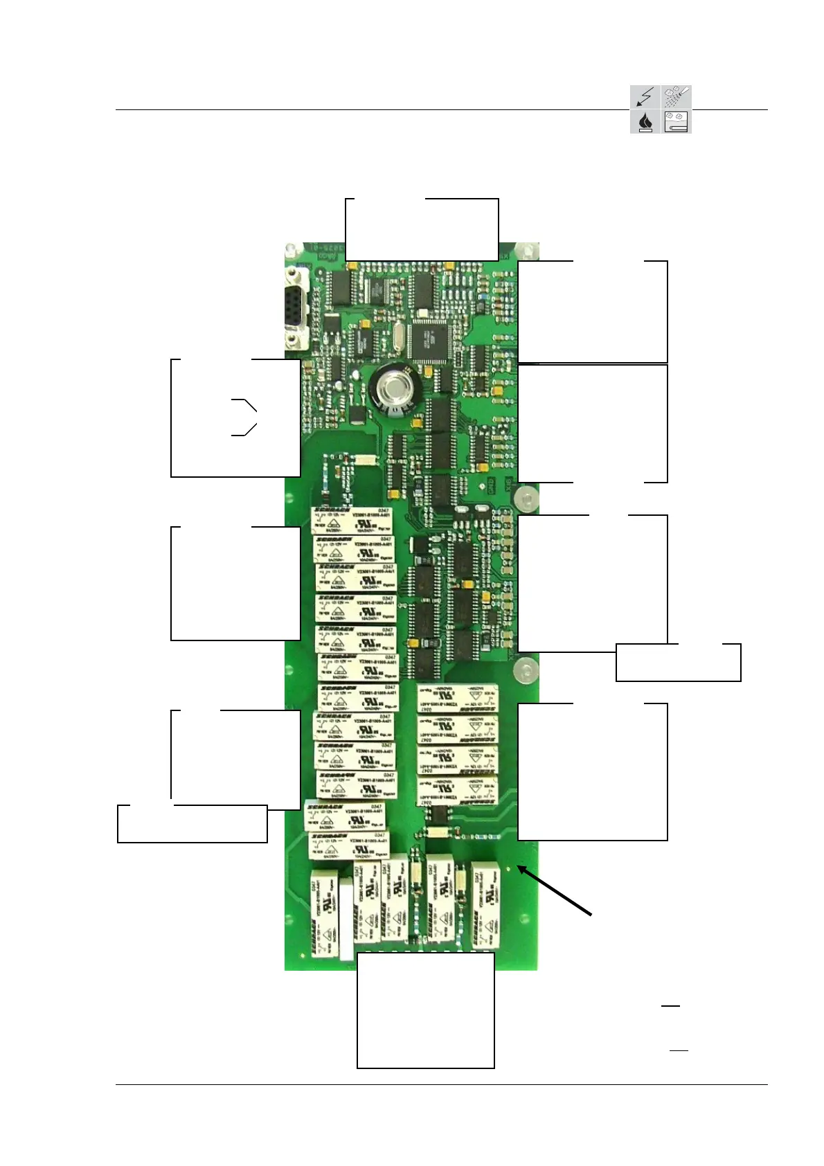
3.5 Controller assignment diagram
3.5.2 Control module CM
with the OGB and OGS
Page 2 / 4
*
= Only with the OSG with one gas burner
*²
= not used with frequency converter
*³
= Only with the OSG with one gas burner
and single phase
CM
rticle no. 5012003
rticle no. 5002094
X17
rticle no. 5012004
X16
rticle no. 5002094
X14
Communication port
Article no. 5009315
OGB - OGS
1 SG pump (OGB)
2 not used
3 SV water nozzle
4 Pump C. Care
5 not used
6 Pump cleaning agent
7 not used
8 not used
9 not used
1 Auxiliary fan (-)
2 Auxiliary fan (+)
3 12V
4 Earth
5 Earth
6 RxD_12V
7 TxD_12V
8 RESET
9 IDM bk
10 IDM wt
11 IDM bl
12 IDM rd
Gas module or
frequency
OGB - OGS
X11
rticle no. 5012002
1 Thermop. Motor *
2 Thermop. Motor *²
3 Motor anti-clockwise *²
4 Motor clockwise *²
5 Motor fast *²
6 Motor slow *²
7 not used
8 Burner supply
OGB - OGS
1 Phase
2 Oven light
3
Heat demand HA1*
4 SV injection
5 SV condenser
6 SV demoisturising
7 not used
OGB
7 SV steam generator filling
rticle no.
X12
OGS
12 (-)
11 Condenser
10 (-)
9 Bypass
8 (-)
7 Oven
6 (-)
5 CTS4
4 CTS3
3 CTS2
2 CTS1
1 ESD protection (CTS-GRD)
OGB - OGS
10 (-)
9 not used
8 (-)
7 not used
6 (-)
5 not used
4 (-)
3 STL steam generator
2 (-)
1Steam
enerato
OGB - OGS
14 not used
13 not used
12 Flame OK HA1*
11 +12V (for Hall sensor) M1
10 GND M1
9 Motor speed M1
8 PWM HA1*
7 GND
6 Pressure cleaning
5 GND
4 Door
3 GND
2 Burner speed HA1*
1 Water pressure
OGB
2 Bottom level
1 Upper
level
X15
rticle no. 5012003
OGS
10 not used
9 not used
8 not used
7 not used
6 not used
5 not used
4 Reset HA1*
3 Reset HA1*
2 Alarm gas HA1*
1Alarm
as HA1*
OGB - OGS
X18
X19
X10
rticle no. 5012003
X13
AS/11-2011 3_05e Controller assignment diagram _d
 Loading...