3. Installation 9752 Installation Guide
Page 16 497098 Issue 3
Fitting the System
Fitting the Control Unit Case
1. Remove the control unit case from its packaging.
2. Remove the front screws and slide off the case lid.
3. The upper part of the case back has a central keyway. Mark and drill a
hole for the keyway. Temporarily fix the case back to the wall. Mark the
position of two more fixing holes, remove the case back and drill the
holes.
4. Refit the case back to the wall using screws no less than 30mm x No 8,
with dome or pan heads.
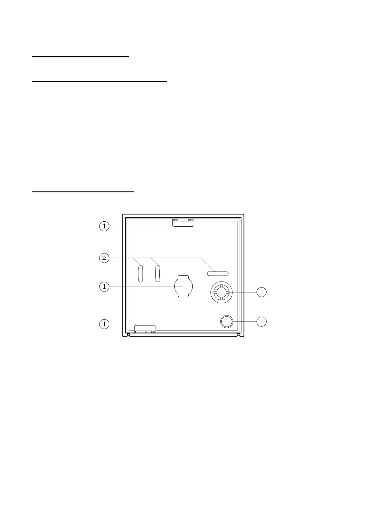
Fitting a 9940 Keypad
Figure 5 shows the backplate and the position of mounting holes.
3
4
Figure 5. Backplate of the 9940 Keypad
1. Cable entry. 3. Back tamper aperture.
2. Fixing holes. 4. Sounder aperture.
It is recommended that you mount the keypad using No 8 or 6 screws
(M4/M3.5) as follows:
1. Select which cable entry you are going to use and break out the
appropriate plastic sections.
2. Hold the backplate in place against the wall and mark the position of one
Þxing hole.
3. Drill and plug the hole, and screw the backplate to the wall. Do not
tighten the screw completely home.
 Loading...
