3. Installation 9752 Installation Guide
Page 20 497098 Issue 3
Keypads
Connecting Keypads
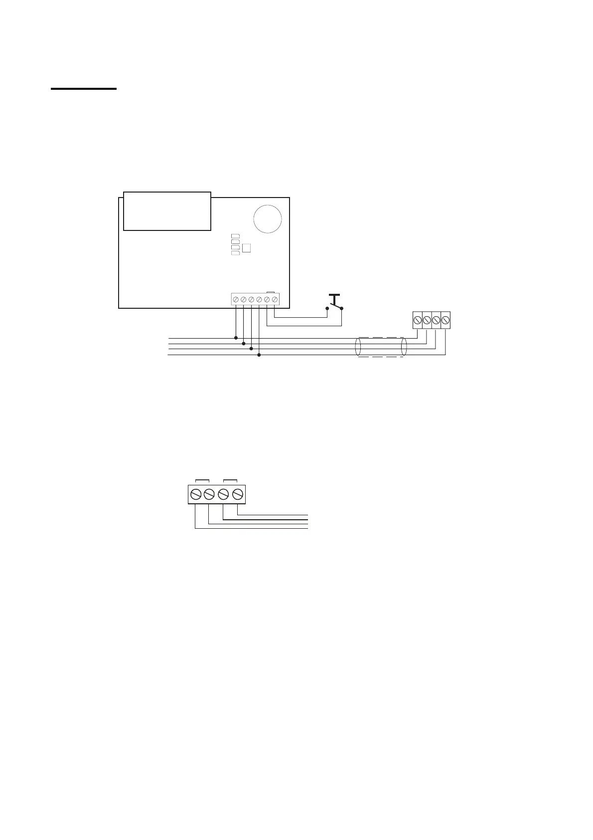
Figure 11 shows the connections for keypads. Use the "ET" connector
terminals on the keypad PCB to connect an exit terminate button or lock
switch. If you are using a lock switch, do not connect any other devices to
these terminals.
4-core
9930 Keypad
0V12V CLK DATA ET
Lock Switch
Or
Exit terminate button
(NO, push to make)
To other
keypads
CLK DATA0V12V
Control Unit
Figure 11. Keypad Connections
The 9940 keypad can be connected to an external panic attack button, as
shown in Figure 12. If the panic attack does not contain a tamper switch, link
the pair of "EXT TAMPER" terminals. Separately link both pairs of terminals if
no panic button is used.
PANIC I/P EXT TAM PER
External Panic
Attack Button
Figure 12. 9940 Panic Attack Connections
 Loading...
