3. Installation 9752 Installation Guide
Page 28 497098 Issue 3
Programming Outputs
Control unit panel outputs can be programmed using the commands shown in
the table below. Open collector outputs are of a "pull down" type that provides
negative-applied control signals; the system adjusts the output polarity when
you select the output type.
Output Type Command
OP1 voltage-free relay 81
OP2 voltage-free relay 82
OP3 open collector 83
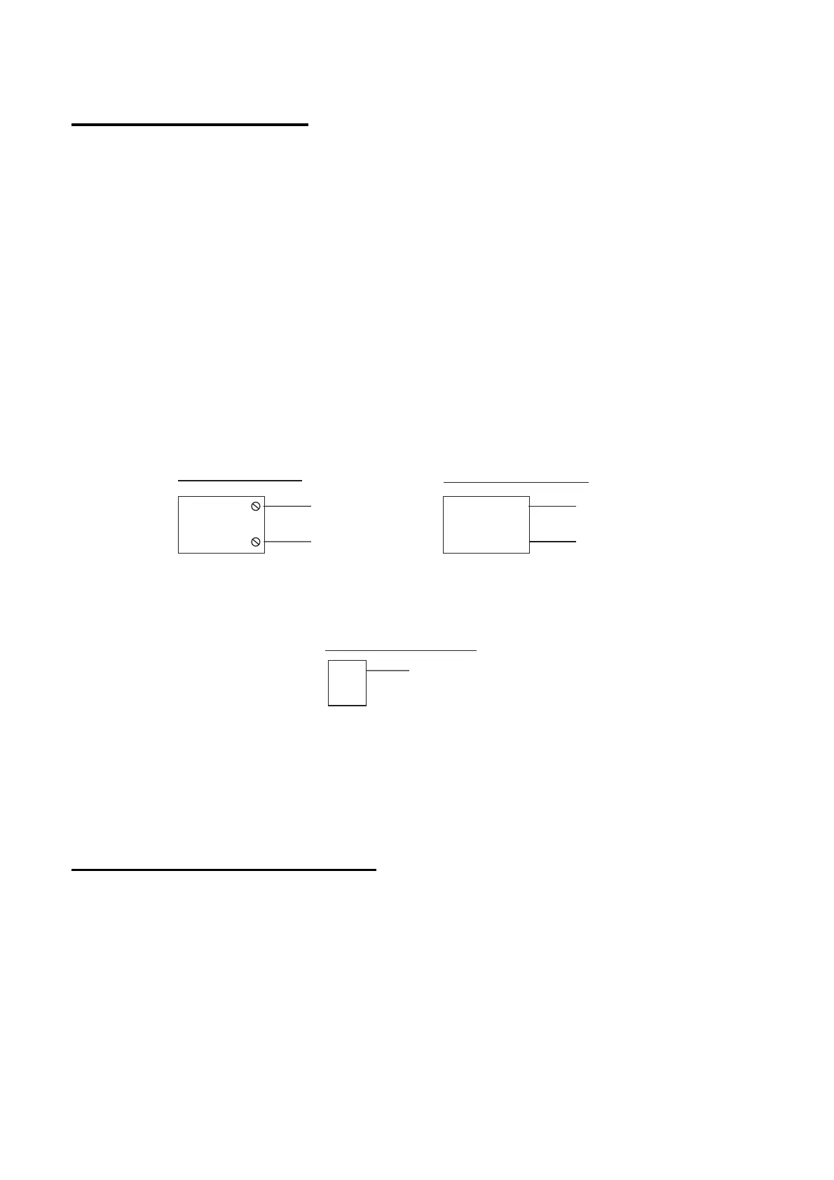
Figure 23 shows some examples of applications for open collector outputs
(OP3 is used in these examples).
OP3
+ve 12V Aux
Shock Sensor Reset
Use Command 83 4
VIPER
+ve
0V
OP3
+ve 12V Aux
Bell Follow Buzzer/Relay
Use Command 83 0
Relay energises/buzzer sounds
when bell activates.
BUZZER/RELAY
OP3
PIR Set Latch/Walk Test
For:
Set Latch use Command 83 3
Walk Test use Command 83 5
PIR
Figure 23. Wiring Examples for Open Collector Outputs
Wiring a Keyswitch Interface
Figure 24 shows the connections for a 9928 Keyswitch Interface. You can fit
only one keyswitch interface in a system.
Note: The keyswitch interface is no longer available for purchase, but is
supported in existing installations.
 Loading...
