3. Installation 9752 Installation Guide
Page 24 497098 Issue 3
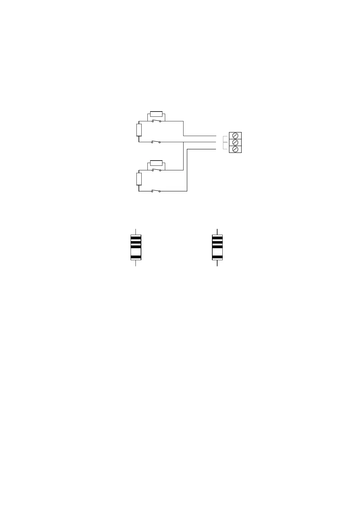
To connect a detector to an FSL loop, you must wire suitable high-tolerance
resistors to the detector. Always check resistor colour coding and tolerance
before wiring resistors into circuit (see Figure 17).
The wiring resistance of the cable to the detector (including joints) should not
exceed 100 ohms. The recommended maximum cable length within a zone is
200–300m.
Zone 1
Zone 2
1
2
2K2 EOL
4K7
Alarm contacts
Tamper contacts
2K2 EOL
4K7
Alarm contacts
Tamper contacts
Figure 16. FSL Connections
Yellow
Violet
Red
Gold
4k7
Red
Red
Red
Gold
2k2
Figure 17. Colour Code for FSL Resistors
 Loading...
