3. Installation 9752 Installation Guide
Page 26 497098 Issue 3
0V 12V CLK DATA
12
14
15
11
8
10
7
9
13
5
6
3
4
2
1
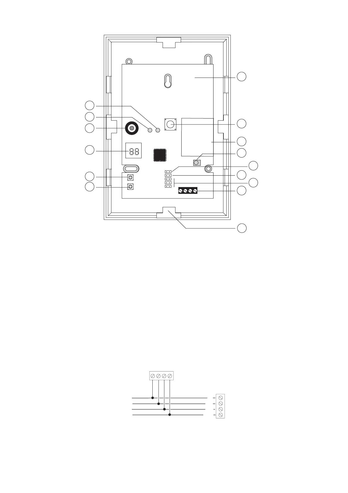
1. Red "Fail" LED 9. Radio section
2. Green "Pass" LED 10. Learn sensor
3. Sounder 11. Supervision jumper
4. 2 x 7-segment display 12. Jamming response jumper
5. Select button 13. Address jumpers
6. Delete button 14. Bus connector
7. Built-in aerial 15. Cable entry
8. Tamper switch
Figure 19. 9960 Radio Expander
Refer to the "9960 Installation and Programming Guide" for more details.
Connecting an Expander
Figure 20 shows how to connect an expander to the control unit.
0V 12V CLK DATA
To other keypads
12V
0V
DATA
CLK
Expander
Control Unit
Figure 20. Connecting a 9954 Expander
 Loading...
