9752 Installation Guide 3. Installation
497098 Issue 3 Page 21
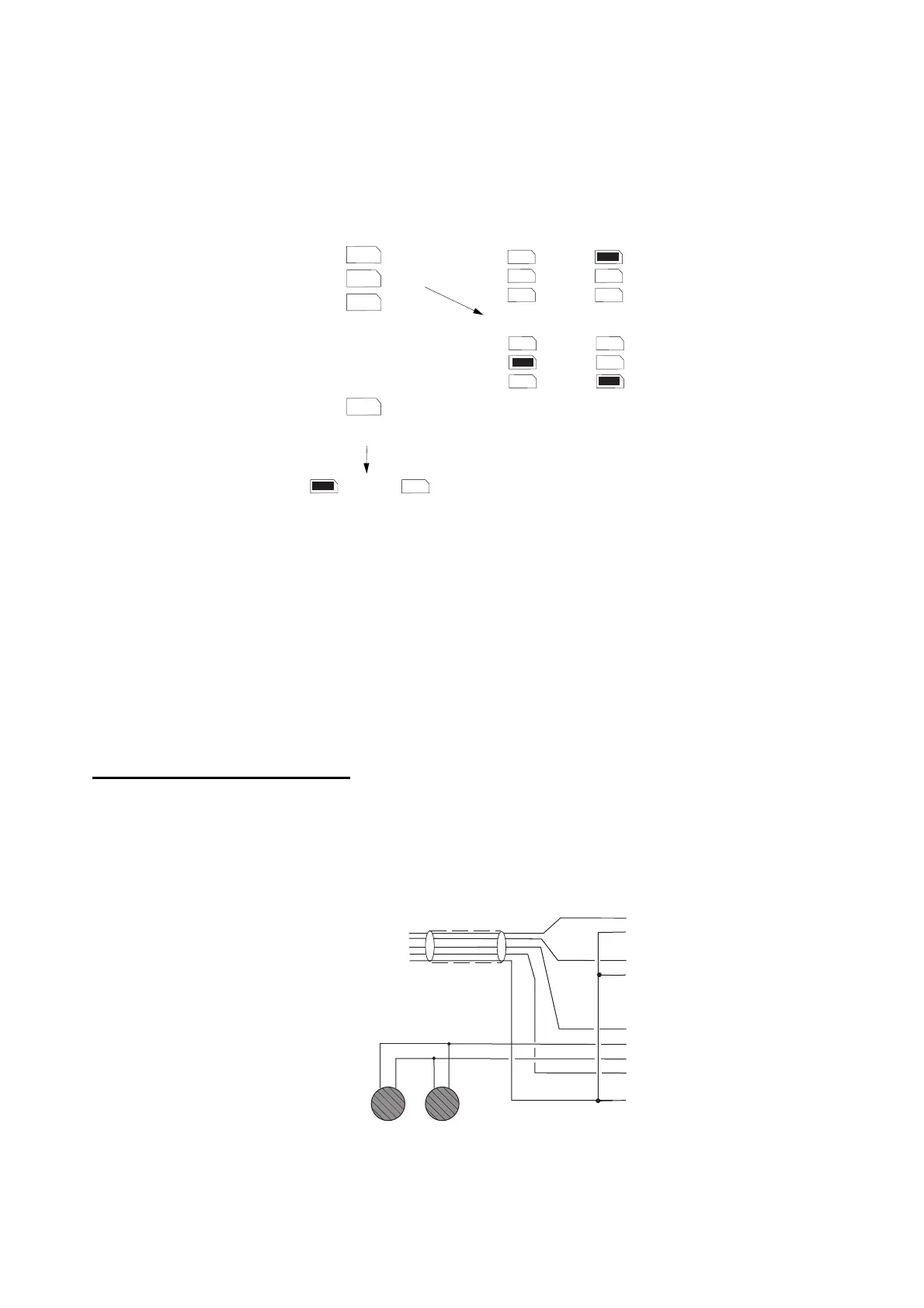
Keypad Addressing
The control unit is supplied with one keypad. If you have fitted more keypads,
each one must be given a separate "address". Links LK2 to LK4 set the
keypad address, as shown in Figure 13.
2
3
4
ON
BACKLIGHT
2
3
4
2
3
4
2
3
4
2
3
4
ON
BACKLIGHT
ON
BACKLIGHT
Keypad 1
Address
Backlight ON Backlight OFF
Keypad 2
Keypad 3 Keypad 4
Figure 13. Keypad Addressing
Backlight
When supplied from the factory, the control unit is configured with the
backlight On. To turn the backlight Off, remove the jumper from the "ON
BACKLIGHT" link, shown in Figure 13.
Connecting Sounders
Figure 14 and the following tables show the wiring required to connect the
external sounder (bell box) and optional internal sounders.
Note: If a 2k2 resistor is fitted at the tamper return (TR) terminal at the bell
box, use Command 59 to select this EOL mode of termination.
To Bell Box
16 Ohm Loudspeaker
(2 Max. in parallel)
Internal Sounder
6-core
NO1
C1
NO2
C2
12V AUX
0V
TR
LS
+
Figure 14. Sounder Connections
 Loading...
