INSTALLATION MANUAL INSTALLATION 29
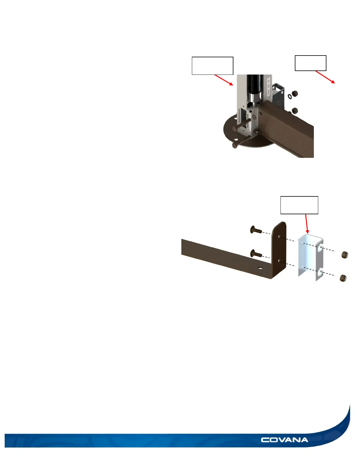
11) Install the long aluminum U-frame over the left
driveshaft and ensure it lines up with motor-side
and non-motor-side jack assemblies. Fasten it
in place using two hexagonal 5/16″-18 x 2″
bolts, two 5/16″-18 nylon-insert lock nuts and
four 5/16″ plastic washers per side, with the 1/2″
(13 mm) socket wrench and spanner. Do not
fully tighten all bolts. The driveshaft may fall
off during operation, and re-assembly can
be done faster when the bolts have not been
fully tightened. (Figure 57)
12) Perform steps 8 to 11 on the opposite side.
13) Install one unpainted metal coupler on each end
of the front frame cut-out. (Figure 58)
14) Align one unpainted metal coupler with the
holes on each end of the front frame cut-out.
Use the provided 1/4″-20 x 3/4″carriage bolts,
1/4″-20 nylon-insert lock nuts and fasten the
hardware with the 7/16″ (11 mm) socket wrench
and spanner. There is one metal coupler per
side. (Figure 58)