35
for each mode.
(1) System check mode for start up, as shown in Figure 4-1:
Figure 4-1 System self check ongoing
This mode indicates that the inverter is checking whether it is ready for
normal operation after the manual start-up of the inverter.
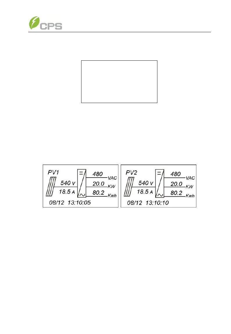
(2) Normal operation mode: Default indication interface for normal
operation of CPS SC20KTL-DO/US-480 & SC14KTL-DO is shown in Figure
4-2 (a) and 4-2 (b). The switching time between (a) and (b) is 5 seconds.
(a) (b)
Figure 4-2 Default indication interface for normal operation
In this mode, the inverter converts the power generated by PV modules to
AC continuously and feeds into the power grid.
(3) Standby mode, as shown in Figure 4-3:
The inverter will turn into standby mode when the output voltage and
power of PV modules do not meet the startup conditions or PV voltage and
input power are lower than the set point. The inverter will check automatically
whether it meets the startup conditions in this mode until it turns back to
normal mode. The inverter will switch from standby mode to fault mode if
malfunction occurs.