48
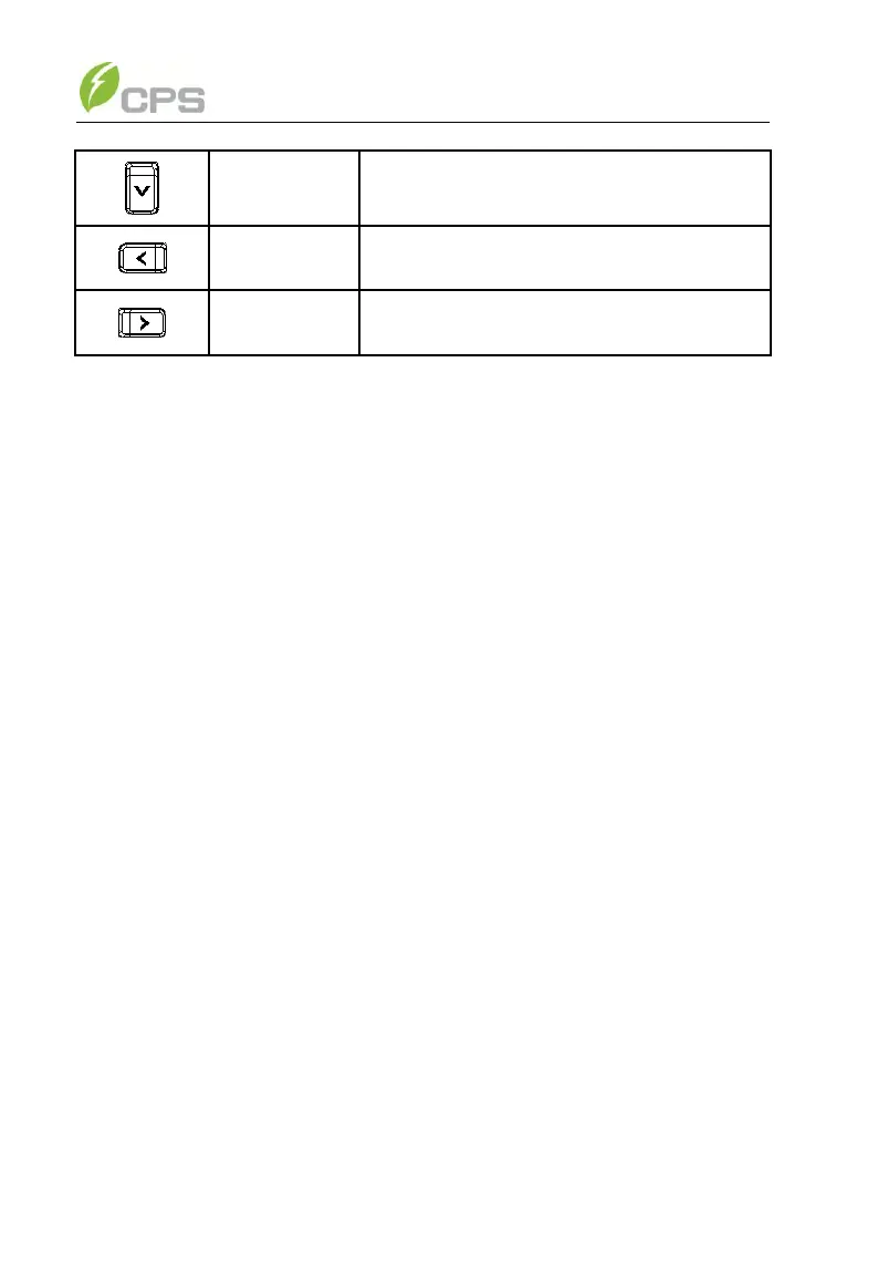
Page down in selection menu
-1 when setting parameters
+1 when setting parameters
5.2 Operation state
Table 5-1 indicates the definitions of LED, i.e. indicates the information of
the inverter’s operation state. It indicates that the system is energized and
under DSP control when “POWER” lights up.
“RUN” will light up when the inverter detects that the grid connection
conditions meet the requirements and power is fed into the grid. “RUN” will
blink if the grid is in derated running state during the period of feeding power
into the grid.
“GRID” will light up when the grid is normal during the operation of the
inverter. Otherwise, “GRID” will blink until the grid restores to normal.
“FAULT” will blink quickly as a fault (except grid abnormality) occurs.
“FAULT” will not light out until the fault is eliminated. The light will blink slowly
when an alarm occurs. “FAULT” keeps being lighted up when an internal fault
occurs.
The buzzer will give alarms if a fault (involving power grid abnormality)
occurs.
5.3 Interface and menu functions
Users can perform the corresponding operations with the 6 function keys
according to the indications of the LCD display.
5.3.1 Interface types
(1) The LCD interface starts with the company logo once the system is