7
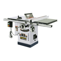
B2397 SAW ASSEMBLY
Remove cast-iron saw table extensions from the carton and set aside.
Remove the table saw from the carton and discard all packing materials
from the cavity of the saw.
Un-wrap the power cord and power switch assembly.
Clean all cast-iron parts with mineral spirits to remove the protective
coating. Thoroughly dry and apply a coat of paste wax and polish.
Carefully mount the saw on the assembled base using the 4 zinc plated
bolts, 8 washers and 4 nuts. The Craftex label on the base should be
facing the front of the saw.
The power cord and on/off switch should be fed down through the top of
the base to be attached to the rip-
fence rail later.
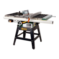
Assemble the two cast-iron extension
tables using the 8 bolts and lock
washers illustrated.
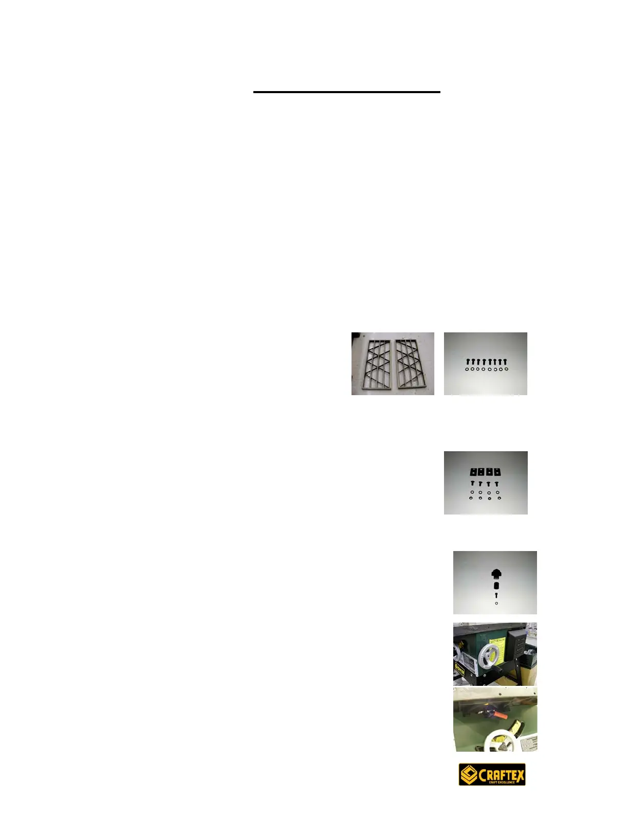
The cast-iron extension tables have holes in the end
edges to accept hangers for the rip-fence front and rear
rail assemblies. Select the 4 large tapered-head philips-
drive machine screws, 4 washers and 4 nuts and attach
the hangers. DO NOT TIGHTEN AT THIS TIME.
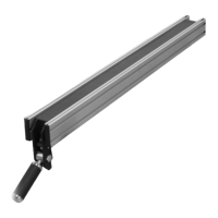
Select the 2 hand-wheels from the parts container, one is for the saw
blade elevation and one is for the blade bevel
adjustment. The blade elevation wheel is fitted with a
shaft bearing and a height lock. Install the bearing, hand-
wheel, lock knob, washer and bolt to the axle and tighten
the bolt.
Install the blade bevel hand-wheel using a machine
screw found in the parts bag.
A separate lock for the bevel angle will be found already
installed above the blade elevation wheel.