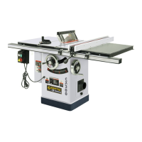
Figure 15
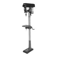
5. Set the table on the stand as in
(Fig.16) and attach using the 5/16-
18 x ½” bolts.
Figure 16
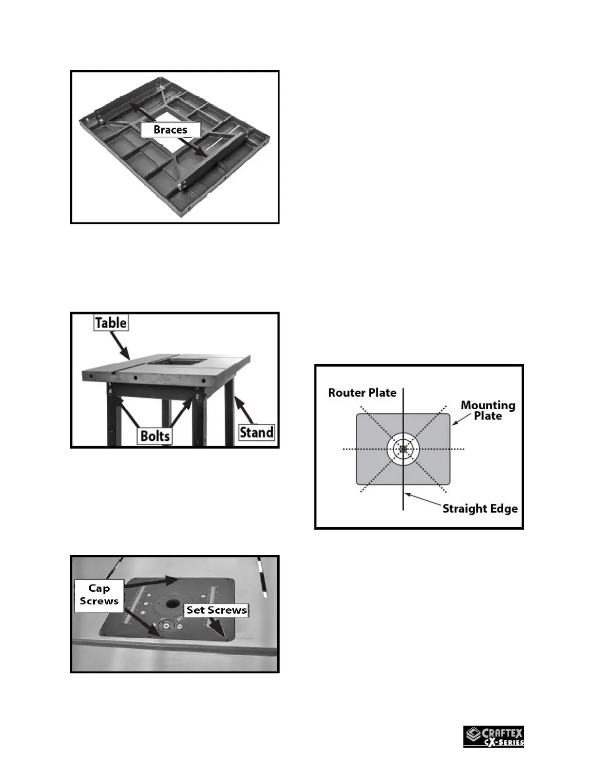
6. Set the Router Lift Assembly into
the table opening with the
mounting plate flush with the top
surface. (Fig.18)
Figure 18
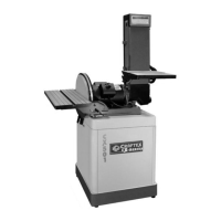
7. To align the Router Lift Assembly
to the table surface, lay a
straightedge across the plate
insert and table surfaces in a
pattern shown in (Fig.19). Then
adjust the set screws (Fig.18) so
that the ends of the straight edge
lay flat on the surface in all
positions of the pattern in (Fig.19).
It is IMPORTANT that this procedure
is done correctly to ensure the
workpiece does not catch on the
edges of the table insert or table
surface and cause kickback.
Figure 19
8. After step (7) is completed, secure
the position with the (2) M4-.7 x
16 cap screws shown in (Fig.18).
9. Secure the Dust Shroud to the
back of the Fence Base with (2) ¼-

 Loading...