4.5.8 Removal of the device’s “scanning plaorm fixaon bracket”
4.5.9 Removal of the device’s"driving rod fixaon bracket”
4.5.10
4.5.11 Cut and remove all secure strips(RED color)
4.5.12 Put back the covers or casing onto the device
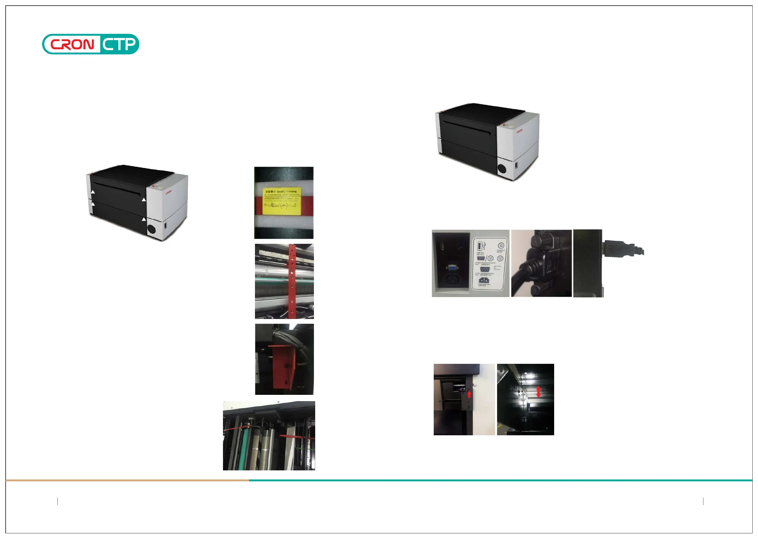
4.5.13 Connecng USB communicaon cable to the Computer
4.5.14 Auto Plate Feeder connecon, installaon and alignment of plate entrance with main device
Chapter 4: Offloading, Unboxing and Installing
a) Scanning Plaorm fixaon bracket is located inside the device. Remove the upper rear casing of the CTP. You
may nocethe "scanning plaorm fixaon bracket" (in RED color) inside the right sideof the device;
b) Use a hex wrench to remove the fixing screws of the "Scanning Plaorm Fixaon Bracket" of the device and
pay special aenon when removal; Handle with care and avoid scratches to the Encoder Strip(gold color) that
aached at the side of the panel along the guide rail
Remove both pieces(L/R) of the "fixing brackets" of
the nozzles sucon arm (on H model), near the front plate
entrance. Remind to keep the hex screws for use to fixing
the loading table later on.
Using an external USB interface cable to connect device and computer, the cable is located in the
lower right side of the enclosure, and it is fastened to ensure reliable connection;
a) Hex screws retained are first used secure onto the reserved front screws holes, but do not
completely tight in
b) Attach the plate loading table to aligned with the hex screws put in before, then secure and tighten
this screws to hold the plate loading table leveled with the main device
1716
SIMPLE AND DIRECT 丨 STEADY 丨 MAJOR
SIMPLE AND DIRECT 丨 STEADY 丨 MAJOR