Released on 10/31/05 - X800058A UV Pure Technologies Inc. © 2005
No part of this document may be photocopied, reproduced, transmitted, or translated to another language without the
prior written consent of UV Pure Technologies Inc.
For additional info call 1-888-407-9997 or email info@uvpure.com
or visit www.uvpure.com
11
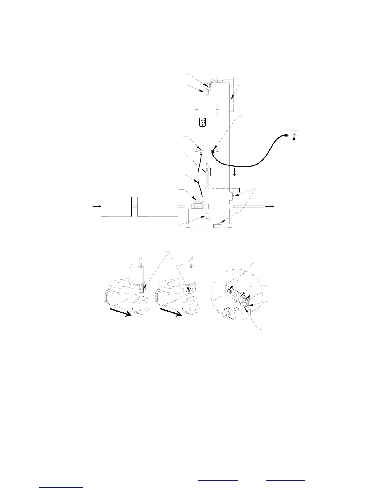
Assembling the Unit
OPTIONAL BYPASS
PIPING & DRAIN VALVE
FROM WATER
SOURCE
TO HOUSEHOLD
PIPING
SOLENOID VALVE
(TEST VALVE MONTHLY)
FLEXIBLE TUBING
FLEXIBLE TUBING
COPPER TUBING
OR EQUIVALENT.
DO NOT USE PVC.
GROUNDED
OUTLET
120VAC 50/60 OR
220-240VAC 50/60 Hz
SEE PAGE 1 OF MANUAL
OPTIONAL DRAIN VALVE
OPTIONAL BYPASS
VALVES
PRETREATMENT
DEVICES
POWER CORD
ENTRY
5x20mm FUSE
& SPARE
VALVE CONNECTOR
FUSE DRAWER
LEVER FOR OVERRIDE
FOR NON REGULATED SITES ONLY
AUTOMATIC
POSITION POSITION
MANUAL
(FORCE OPEN)
PLUG FOR VALVE
(DO NOT CONNECT ANY OTHER
DEVICE IN THIS RECEPTACLE)
F
L
O
W
PIPE INSULATION
(MUST BE INSTALLED)
SECURE CABLE
TO WALL
POWER CORD ENTRY
(LOCATION OF FUSE)
FL
O
W
TYPICAL INSTALLATION
SOLENOID VALVE
POWER INPUT LABEL
PRESSURE
TANK
(ACTS AS CHECK VALVE)
Figure 1B
Step 1: Unpack the unit, being careful to remove all packaging material. Remove
the elastic band stretched around the top of the lamps in the unit and wood
pieces on wall brackets. Inspect the unit for damage particularly the quartz
sleeve – See Figure 4A for disassembly.
Step 2: Connect the Stainless flexible hoses to both the top and bottom of the
Hallett. Remove the top and bottom covers of the unit to make the connection
more accessible. The hose for the top outlet of the Hallett 13 has been pre-bent.
The bottom inlet hose is straight. Both hoses for the Hallett 30 are straight. Make
sure that the sealing washer is inside the hose end before making the
connection. Tighten securely. Wrap the top hose with pipe insulation.


 To Next Page