Released on 10/31/05 - X800058A UV Pure Technologies Inc. © 2005
No part of this document may be photocopied, reproduced, transmitted, or translated to another language without the
prior written consent of UV Pure Technologies Inc.
For additional info call 1-888-407-9997 or email info@uvpure.com
or visit www.uvpure.com
17
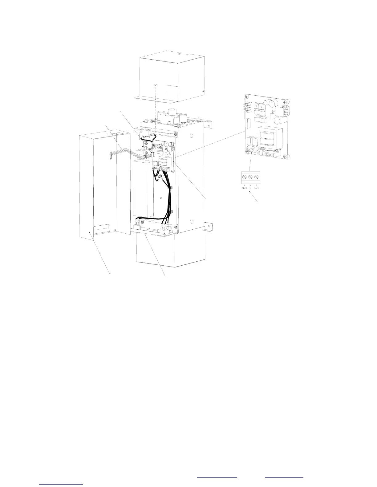
KNOCKOUT
LOCATED
HERE
CIRCUIT BOARD
WITHIN UNIT
TYPICAL HALLETT UNIT
DRY CONTACT TERMINALS
RATED AT 0.5A/125VAC MAX.
DISPLAY RIBBON
CABLE
GRIP CONNECTOR TO
REMOVE
FRONT
COVER
Figure 1F
The front cover must be removed to gain access to external alarm contacts.
This is accomplished by removing the screw that secures the top cover. Remove
the top cover. Gently remove the front cover and hold it a couple of inches off
from the body of the unit. You must disconnect a thin ribbon cable that powers
the display lights – be careful not to damage it. Reach in and disconnect the
ribbon cable from the circuit board by grabbing the end black connector (never
pull on the green cable itself). The front cover will then come free.
Proceed with inspection or repair of unit as required.
When complete, replace the front cover by first reconnecting the 6-pin ribbon
cable to the port marked ‘DISPLAY’ (ensure the black connector is aligned
properly and do not miss any pins). Place the front cover in its rest position.
Replace the top cover and screw it down
 Loading...