Page 12
distance may require 0.5mm² cable. Always use good quality cable. Some installations may require data cable to en-
sure data integrity in noisy sites.
KEYPAD TAMPER (wrong code alarm)
A wrong code or Keypad Tamper alarm is generated by the Elite after 4 consecutive invalid code entries. The con-
troller will not “Lock-Out” the keypad at this point but simply create an alarm condition that may be reported to a
monitoring company via the dialler. Entry of a valid user code will reset the Keypad Tamper alarm, however, the
alarm event will be written into memory and the keypad memory light will be flashing indicating the presence of a new
memory entry.
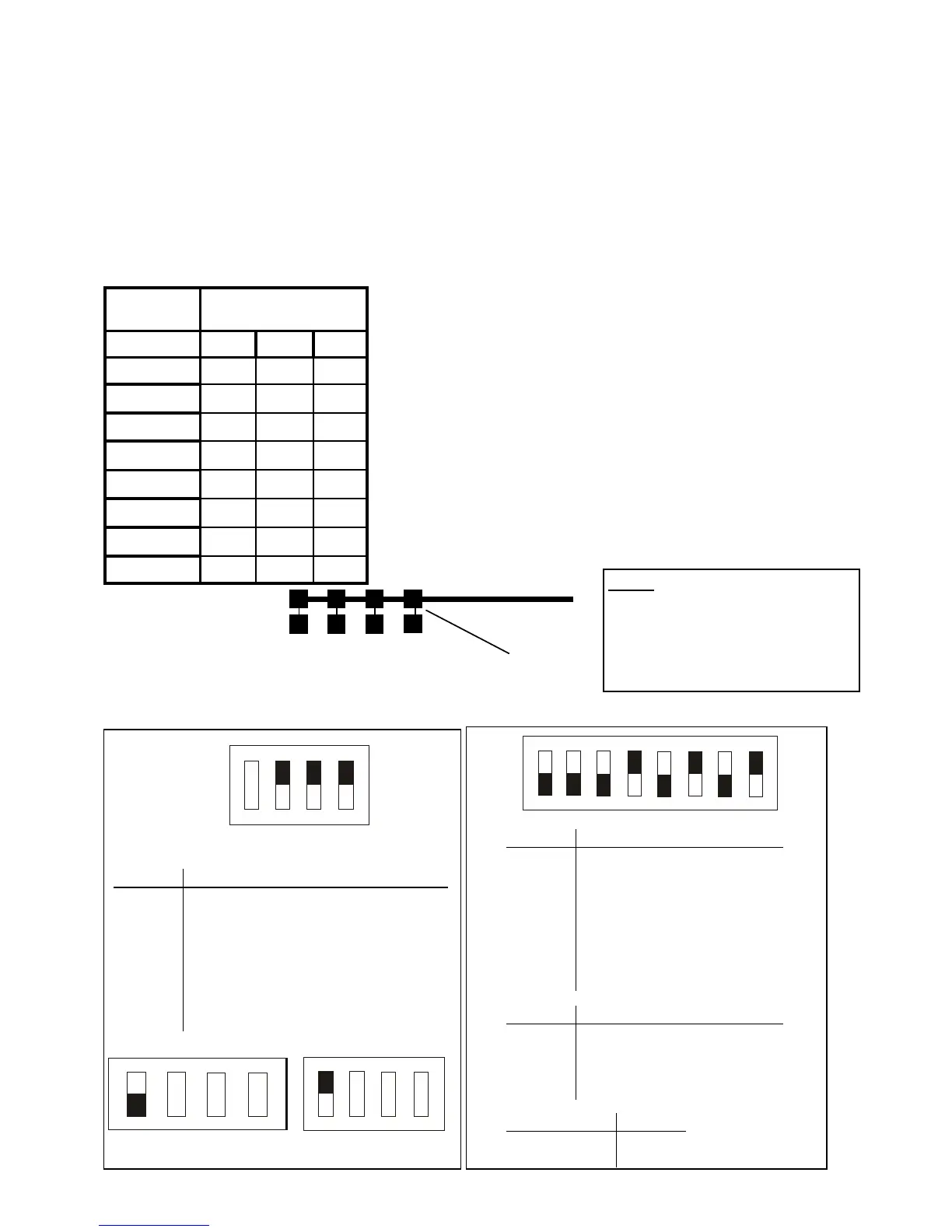
Each of the 8 possible LED keypads which are able to be connected to
your Elite panel must be addressed individually to avoid BUS conflicts and
other communication problems. As default, each keypad comes ad-
dressed as #1 with all links intact.
Use the table to the left to detevmine which links to cut to assign the cor-
rect address to the keypads you are installing, e.g. To assign a keypad as
address #2, you must cut link A only. To assign a keypad as address # 4,
you must cut link A&B.
When cutting address links it is important to make a clean cut between the
link blocks as shown below. Links can be restored by soldering across the
effected pads.
IMPORTANT NOTE: KEYPAD ADDRESS CHANGES ARE ONLY REC-
OGNISED AT POWER-UP. ALL CHANGES SHOULD BE MADE IN THE
POWERED DOWN STATE AND THEN ON POWER-UP THE NEW KEY-
PAD ADDRESS WILL BE RECOGNISED BY THE PANEL.
Keypad
Address
Address
Links
#
A B C
1
2
X
3
X
4
X X
5
X
6
X X
7
X X
8
X X X
X denotes link is cut
A B C
D
cut here
ADDRESSING ORIGINAL (CUTTING LINK) TYPE KEYPADS
1 2 3 4 5 6 7 8
On
Off
Switch '1' Switch '2' Switch '3'
Keypad 1 Off Off Off
Keypad 2 On Off Off
Keypad 3 Off On Off
Keypad 4 On On Off
Keypad 5 Off Off On
Keypad 6 On Off On
Keypad 7 Off On On
Keypad 8 On On On
Panel Switch '5' Switch '6' Switch '7'
PW-4 Off Off Off
PW-8 On Off Off
PW-16 Off On Off
PW-64 On On Off
Switch '8'
Disable Tamper On
Enable Tamper Off
Addressing new LCD Keypads
Addressing new Icon Keypads
NOTE:
ONLY the latest (Series-6) Icon (LED
Type) and the newer LCD (Ver:1.04)
type keypads are compatible with this
(Ver:6.20) panel. The keypads from the
previous (Ver:5.xx) panel are NOT
compatible with this (Ver:6.20) panel.
D C B A
Keypad 1 On On On
Keypad 2 On On Off
Keypad 3 On Off On
Keypad 4 On Off Off
Keypad 5 Off On On
Keypad 6 Off On Off
Keypad 7 Off Off On
Keypad 8 Off Off Off
Tamper Disable
D C B A
Tamper Enable
D C B A
Keypad 1
default
D C B A
Off
On
Off
On