Page 8
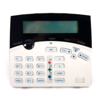
KEYPAD LED or LCD INSTALLATION
INSTALLATION
Remove the Well Mount Bracket (Back cover) by unscrewing the holding screw at the bottom side.
Screw the bracket to the wall using the mounting holes provided with the necessary number of screws.
Make sure the base is mounted right side up.
When fixing the bracket to the wall make sure the top of the screw heads will not touch or short out the underside
of the PCB when the top half of the keypad is reinstalled.
Insert the wire through the wire access hole at centre of the base.
Connect the 4 wires to the 4 way terminal block on the back side of the keypad PCB, make sure to match the
cables up with the terminals as marked on the control panel's keypad port.
Once the cables have been terminated and the required address allocated (see section below) replace the front
half of the keypad onto the bracket by first engaging the clips at the top edge and then close the front down and
screw it in at the bottom. Now stick the zone list provided to the inside of the keypad cover.
WIRING
The PW4 keypad connects to the PW-4 Controller via a 4 wire data security cable. A maximum of 8 keypads
can be connected, each wired in parallel.
The maximum recommended cable using standard 0.2mm security cable is 50m. Cable runs exceeding this
distance may require 0.5mm cable. Always use good quality cable. Some installations may require CAT5 data
cable to ensure data integrity in noisy sites.
User information :
Keypad LCD — Power Wave CR16M-LCD Keypad
Users’ Operating and Programming Guide
Keypad LED — Power Wave – 4
Users’ Operating and Programming Guide
When the PW-4 is displaying codes and address values in program mode it may be necessary to display the
9 and 0 digits. As there are no Zone indicators for 0 and 9 the "A" and "B" indicators are used.
i.e.. When displaying values in program mode
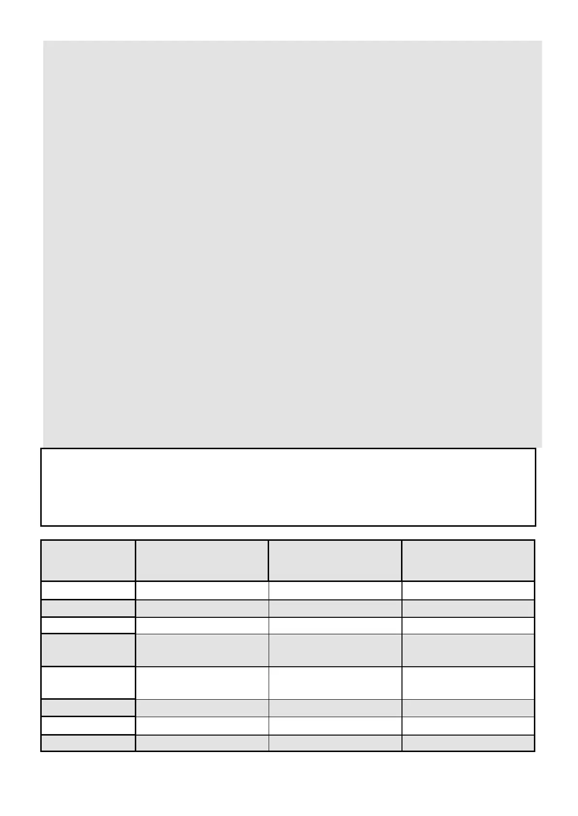
LIGHT\INDICATION
OFF
ON STEADY
FLASHING
READY\BYP Zone Unsealed All Zones Sealed A Zone is bypassed
SYSTEM
Normal System Alarm Reset New System Alarm
TROUBLE
Normal Trouble Alarm Active New Trouble Alarm
PROGRAM Run Mode Client Program Mode Installer Program Mode or
Control Function Active
READY\BYP
& PROGRAM
- Bypass Mode Active
(Zones can be Bypassed)
-
ZONES 1-4
Zone Secure Zone Violated Zone in Alarm
Armed A
Partition A Disarmed Partition A Armed Partition A STAY Mode
Armed B
Partition B Disarmed Partition B Armed Partition B STAY Mode