Page 9
VIEW MEMORY MODE
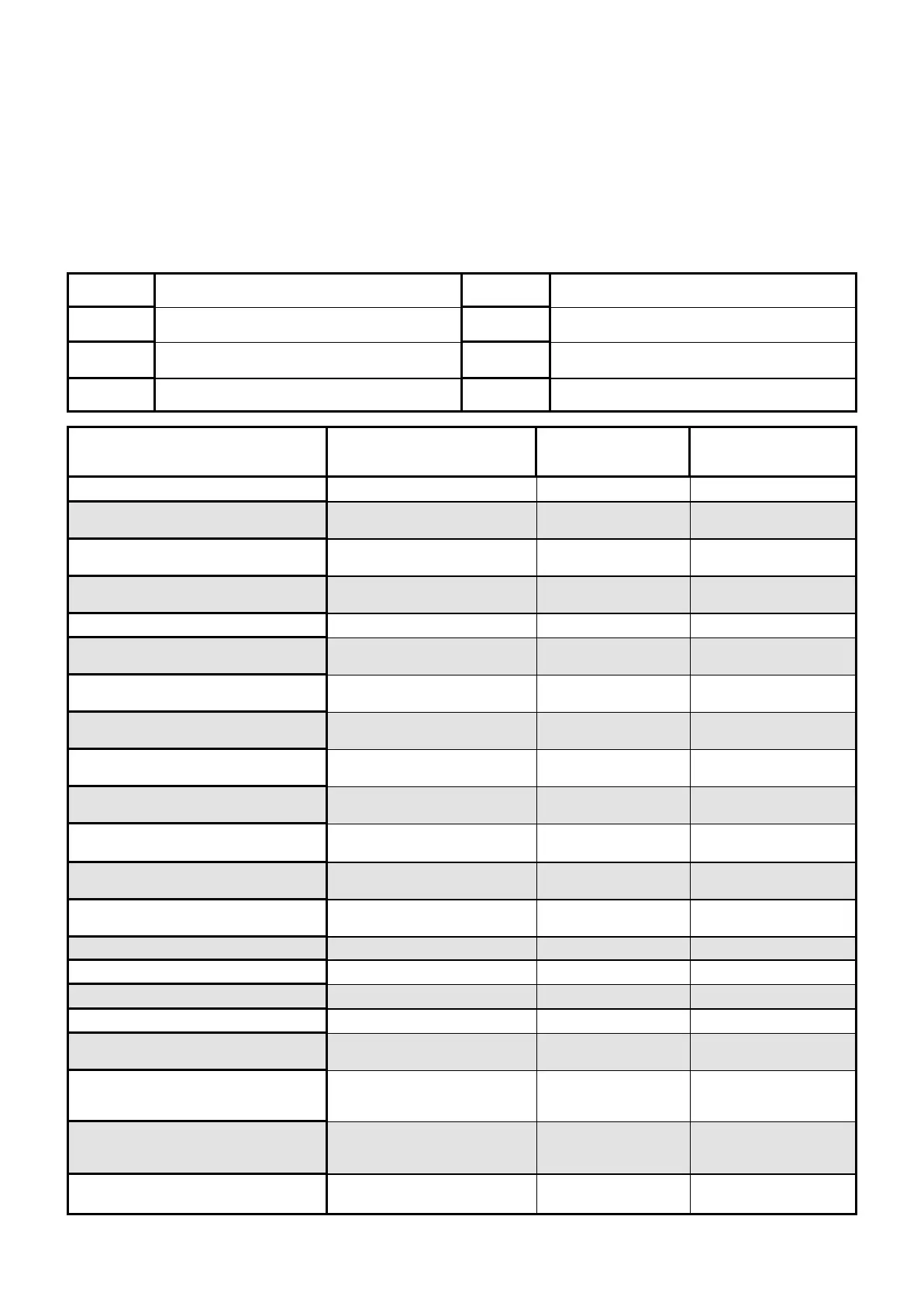
EVENT TYPE \ INDICATION
?
DEVICE INDICATOR STATUS
ACTIVATION Zones 1-4 LED's 1-4 On Steady
BYPASS Zones 1-4 READY/BYPL
LED's 1-4
On Steady
On Steady
DETECTOR TAMPER
(SHORT CIRCUIT)
Zones 1-4 TROUBLE
LED's 1-4
Flashing
On Steady
DETECTOR TAMPER
(OPEN CIRCUIT)
Zones 1-4 TROUBLE
LED's 5-8
Flashing
On Steady
CABINET TAMPER
Cabinet or Satellite Siren TROUBLE Flashing
LOW BATTERY Controller Battery SYSTEM
LED 1
On Steady
On Steady
MAINS FAILURE Controller Mains Supply SYSTEM
LED 2
On Steady
On Steady
RADIO ZONE LOW BATTERY Radio PIR
Zone 1-4
LED's 1-4 Flashing
PENDANT LOW BATTERY
Radio Key
User 1-4
TROUBLE
LED's 1-4
On Steady
Flashing
PANIC BUTTON (or BUTTONS
1&3 PRESSED TOGETHER)
Keypad Panic SYSTEM Flashing
FIRE ALARM (BUTTONS 4&6 PRESSED
TOGETHER)
Keypad Fire SYSTEM
AREA A
Flashing
Flashing
MEDICAL ALARM (BUTTONS 7&9
PRESSED TOGETHER)
Keypad Medical SYSTEM
AREA B
Flashing
Flashing
PENDANT PANIC
Radio Key
User 1-4
SYSTEM
LED 1-4
Flashing
Flashing
ARMED A
Area A is Armed AREA A On Steady
ARMED B
Area B is Armed AREA B On Steady
STAY MODE A Area A STAY Mode ON AREA A Flashing
STAY MODE B
Area B STAY Mode ON AREA B Flashing
DURESS ALARM
Duress Alarm TROUBLE
AREA A & B
On Steady
Flashing
SUPERVISED RADIO ALARM
Supervised Radio
Passive Infra-Red
SYSTEM
TROUBLE
LED’s 1-4
On Steady
Flashing
Flashing
ZONE INACTIVITY ALARM Zones 1-4 READY/EXCL
TROUBLE
LED’s 1-4
On Steady
On Steady
On Steady
TELEPHONE LINE FAILURE
Phone Line Failure SYSTEM
LED 3
On Steady
On Steady
When viewing the memory event buffer at the keypad by pressing the “MEMORY” button, the first thing that will
always be displayed is the “SYSTEM” LED. If the system led turns on but no other Zone LED’s are on at the same
time, this means that there are no current system alarms. If a zone LED or LED’s are On then this indicates sys-
tem alarms that have not yet cleared. The zone LED’s 1-4 are pre-defined as to what system alarm they will dis-
play. These system alarm indications are shown in the table below. Following the display of current system alarms
the panel will then sequence through the 127 historical memory events starting at the most recent event. The sec-
ond table shows the alarm events that can be displayed in memory mode and what indicators are used to show
them.
LED # 1
Battery Low
LED # 5
Radio Pendant Battery Low
LED # 2 Mains Failure LED # 6 Supervised Detector Failure
LED # 3
Telephone Line Failure
LED # 7
Zone Inactivity Timeout
LED # 4 Radio Detector Battery Low LED # 8 Dialer Kiss-off Failure