EasyManua.ls Logo

Crow PowerWave-4 - User Manual

Crow PowerWave-4
64 pages
Print Icon
To Next Page IconTo Next Page
Loading...
ELECTRONIC ENGINEERING LTD.
4 Zone Control Panel Communicator
PowerWave- 4
P/N 7111346 Rev. B M.E/Y.S/N.A
Version 8.63 07/2002
Installation and
Programming Guide
Page 1
1
2
3
4
A
5
6
7
8
B
Ready-Byp
System
Trouble
Program
7
4
1
2
3
5
6
9
8
0
ENTER
PROGRAM
BYPASS
STAY
ARM
C
O
N
T
R
O
L
M
E
M
O
R
Y
P
A
N
I
C

Table of Contents

Question and Answer IconNeed help?

Do you have a question about the Crow PowerWave-4 and is the answer not in the manual?

Summary

Connection Diagram

Keypad

Diagram showing keypad connection to the PW-4 control panel.

Inputs

Zone Inputs

Configuration options for the 4 zone inputs, including EOL resistor types.

Outputs

12 Volt Outputs

Details on the two 12 volt DC outputs available on the PW-4 PCB.

PW-4 Keypad Options

LCD-Keypad

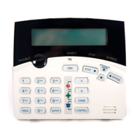
Features and indicators for the LCD keypad model.

Keypad LED or LCD Installation

Installation

Instructions for mounting and wiring the keypad to the control panel.

LED Keypad Address Assignment

Programming Your PW-4

How to Program

General sequence and methods for programming the PW-4 control panel.

Programming User Codes

User Code Options

Mapping Zone Alarms to Outputs

Partition A Options

Partition B Options

Programming Entry Delays

Output Timing Options

Output Reset Time-P311 E-P318 E (0-9999 Seconds)

Defines how long an output stays on after an alarm condition.

Keypads with Panic Button Enabled

Restore Factory Defaults

Dialer Programming Section

Programming Telephone Numbers

Armed by User 4+2 Code

PW-4 Program Summary Guide

Contact ID Code Summary

Crow PowerWave-4 Specifications

General IconGeneral
BrandCrow
ModelPowerWave-4
CategoryCell Phone
LanguageEnglish