MA-5002VZ Service Manual
4-12 Circuit Theory
130446-1 Rev. A
©2000 Crown International, Inc.
shutdown. A low will also cause the DC/LF red LED on
the main module to light. DC/LF is a non-latching pro-
tection mechanism.
4.6.4 Common Mode Output Current
Common mode current in the output stage
can only be due to an output stage failure
or full power output of RF energy. Com-
mon mode current occurs when a high
current level exists in both the positive and
the negative halves of the output stage.
U115 is a specialty device. It serves as
both an Opto-SCR, and as a conventional
SCR. It must have both an optic gate and
conventional gate firing at the same time
in order to latch. The conventional gate is
fired by current sense of the output stage
Low-side. The optic gate is fired by the
High-side current sense. If high currents
exist in both sides simultaneously, the SCR
will latch on, and remain on until the unit is
turned off.
When the SCR latches, low voltage causes
the red LED (labeled Output Module) to
light, and places a low on the FAULT sig-
nal line. A low on the FAULT line is sensed,
via D112, by C120. Once again, a low here
discharges C120 and shuts down the am-
plifier. FAULT is a latching protection
mechanism (the only one in the amplifier).
4.6.5 Output Thermal
Output over-temperature protection has
been covered, to a degree, in Section
4.4.2, ODEP Circuitry. The calibrated tem-
perature sense from the positive half of the
output stage drives an over-temperature
amp, U117A. If heatsink temperature ex-
ceeds a limit of about 130°C, the amplifier
will go into hard ODEP. This does not shut
down the amplifier, but does clamp the au-
dio. Refer to Section 4.4.2.
4.6.6 Transformer Thermal
The main power transformers have built-in thermal
switches which open in the event of transformer over-
temperature. In the event that the thermal switch opens
in the channel 1 toroid, Q709 turns on, causing U707D
to go low. When it does, the over-voltage/thermal switch
LED on the control module is energized and the OV1
signal is tripped; the fans are also forced to high speed.
Transformer thermal protection is self-resetting. This
results in amplifier shutdown by way of shared over-
voltage circuitry. Refer to Section 4.6.2.
4.6.7 FET Thermal
A special circuit has been designed into the MA-5002VZ
to protect the MOSFET switches in the VZ supply. The
voltage drop across the FETs (while conducting) is pro-
portional to device temperature. Control circuitry senses
the voltage and, if necessary, the supply will be forced
into low voltage (high current) mode to allow the FET
devices to cool.
DC PULSE
WIDTH
CONTROL
-
+
+10.4V
MAIN
RELAY
-
+
SOFT-
START
OVER-VOLTAGE
-
+
TOROID
THERMAL
SWITCH
±15VDC
SENSE
FAULT
SENSE
LS NPN CURRENT
HS NPN CURRENT
±LL & ±LH
FOR LS BIAS &
V XLTR FEED
CONTROL
DC VOLTAGE &
CURRENT SENSE
To Ch 2
To Ch 2
OV/TSW
OV/TSW
RED
x1 BUFFER
PWR LOSS
OUTPUT
MODULE
RED
FAULT
DC/LF
DC/LF
RED
-15V
+15V
C120
PWR
STANDBY
SOFT-START
CONTROL
01
V
REMOTE
STANDBY
FROM PIP
STBY
RED
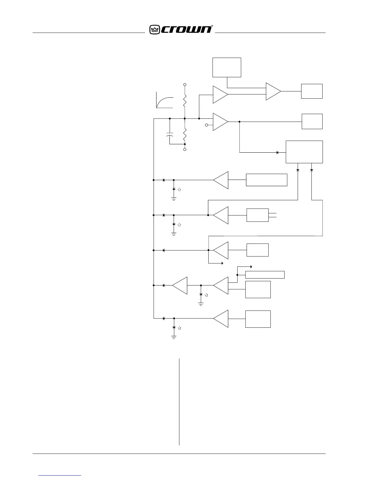
Figure 4.8 Over-all Protection Scheme

 Loading...


