MA-5002VZ Service Manual
5-8 Maintenance
130446-1 Rev. A
©2000 Crown International, Inc.
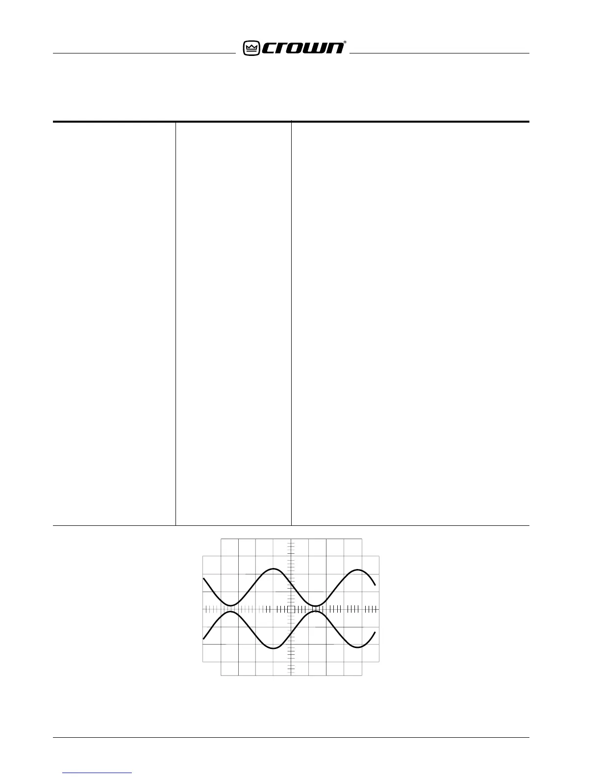
10. Parallel Mono 1-kHz Sine Wave
No Load
11. Current Sense Balance No Signal
No Load
12. Static Balance No Signal
No Load
13. Dynamic Balance 1-kHz Sine Wave
No Load
Note: Always turn power to the amplifier off prior to
changing the position of the Stereo/Mono Switch.
With
the dual/mono switch in the parallel mono position,
insert a .775 Vrms 1-kHz signal into channel one. There
should be two signals with the same polarity present,
equal in amplitude, at the outputs of channels one
and two. Both of these signals will be controlled by
the channel one input level control. Switch the stereo/
mono switch to stereo. There should be signal present
only on the channel one output.
Place the Stereo/Mono switch in the PARALLEL MONO
position. Measure VDC of the channel 1 + output with
respect to the channel 2 + output. Verify null of less
than ±10 mVDC. If necessary adjust null via R2 cur-
rent sense balance pot on the Main Module.
Place the VZ Mode switches in the VZ-ODEP position
(see Figure 5.4). Measure ±VCC with respect to
ground for channel 1 (P852 & P851 on Control board).
Values should be of equal magnitude and opposite
polarity. If magnitudes vary by more than 500mV, ad-
just static balance pot R568 on the output module for
null (no difference in magnitude). Switch to VZ (AUTO)
position and verify null is maintained. Re-adjust only
if necessary. Repeat check for channel 2 (P854 & P853
on Control board), adjust R568 if necessary.
With no load on the amplifier, increase the input to
achieve 125.0 Vrms, ±.3 Vrms, at the output of the
channel under test. Measure TP1/TP2 pin 16 and ad-
just R566 on the output module for 3.500 Vrms, ±.200
Vrms.
Type of Test Input Signal and Comments
or Adjustment Load Parameters
Figure 5.2 Bridge MONO

 Loading...


